
Beam scanning array antenna

An array antenna and beam scanning technology, applied in the field of beam scanning array antennas, can solve the problems of increasing the difficulty and cost of antenna processing, affecting the performance of the antenna, beam scanning, and complexity of the antenna, achieving stable antenna beam scanning function, reducing processing costs, The effect of simplifying the antenna structure

Inactive Publication Date: 2011-04-13
XIDIAN UNIV
View PDF5 Cites 24 Cited by
  • Summary
  • Abstract
  • Description
  • Claims
  • Application Information

AI Technical Summary

Problems solved by technology

Due to the complex actual processing of this antenna, and the loading reactance value of each vibrator changes with the frequency, especially some unknown conditions at the high end of the frequency, such as the jump of reactance characteristics, etc., will affect the performance of the antenna and beam scanning; in addition , due to the existence of parasitic oscillators, the impedance of the active element located in the center is mismatched and it is difficult to obtain a match simply by adjusting the antenna structure or size
[0004] The application number is: 200580016384.5 switchable multi-beam antenna device, which discloses the use of a common reflector in the antenna assembly to control the feed of surrounding monopoles through switches, thereby realizing the multi-beam scanning function. However, for the structure of the common reflector, The size puts forward requirements, which increases the processing difficulty and cost of the antenna
Another example is the directional switching device with the application number: 01801254.X, which discloses that the transmitting vibrator is folded and parasitic vibrators are loaded with reactance elements. Although the folded transmitting vibrator can achieve good impedance matching, the parasitic vibrator still needs to be loaded Reactance elements, which still bring some difficulties to the actual processing of the antenna, and due to the instability of the reactance elements at high frequencies, will affect the performance of the antenna and the switching of beams

Method used


Image

  • Beam scanning array antenna
  • Beam scanning array antenna
  • Beam scanning array antenna

Examples


Embodiment Construction

[0024] A specific embodiment of the present invention is an array antenna whose working frequency band is 2.4 GHz of a wireless communication system and can realize 90° beam scanning.

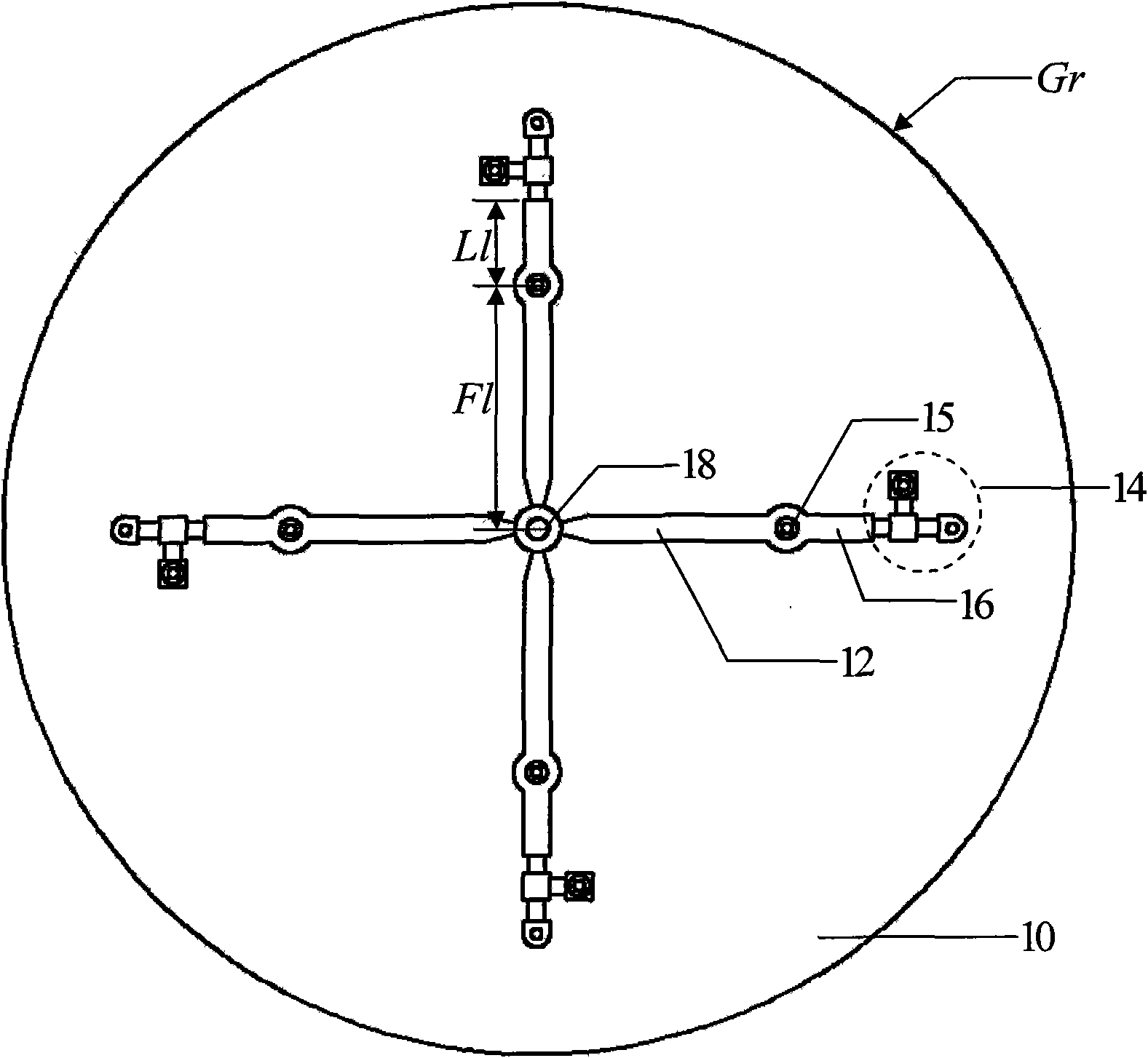
[0025] refer to figure 1 , figure 2 and image 3 , the present invention is mainly composed of a microstrip power distribution feeding part, an antenna vibrator unit, an equivalent inductance loading part and a diode switch control circuit part. in,

[0026] The feeding part includes a one-to-two power distribution feeding network 12 in the form of a microstrip line, a pad 13, a dielectric board 10, an SMA connector 11, and a vertical probe 18, wherein the equal power distribution feeding network adopts a cross structure Etched on the upper surface of a Rogers RT / duroid 5880 dielectric plate 10 with a radius of Gr and a thickness of sh, the feed point is located at the cross point through the vertical probe 18, and the back of the dielectric plate 10 is used as the floor of the antenna syst...


PUM


Abstract

The invention discloses a beam scanning array antenna mainly solving the problems that a traditional passive beam scanning antenna has complicated structure and high loading and processing cost caused by using reactive elements. The whole antenna comprises a microstrip isopower distribution feed network (12), a vibrator unit (15), a feed microstrip extension line (16) and a diode switch control circuit (14), wherein the microstrip isopower distribution feed network (12) is in a cross structure, a feed point is arranged in a cross point through a vertical probe (18) to realize isopower distribution feed, the antenna vibrator unit (15) is fixed at one end of each feed microstrip line, and the feed microstrip extension line (16) is connected with the diode switch control circuit (14) and controls the connection and disconnection between the feed microstrip extension line and a floor at the back of a medium plate (10) to realize wide beam scanning in four different directions. The invention has the advantages of simple structure, low processing cost and easily realized beam scanning function and can be applied to a mobile terminal in a wireless communication system.

Description

technical field [0001] The invention belongs to the technical field of antennas, in particular to a beam scanning array antenna, which can be applied to mobile terminals of wireless communication systems. Background technique [0002] With the hot research on smart antennas at home and abroad in recent years, most of the researches are carried out on smart antennas for base stations. Because the smart antenna used in the base station is installed on the base station of mobile communication, its size is relatively small, so some mechanical parameters of the antenna, such as the number of array elements, array arrangement, array element spacing and array element size, etc. Designing within a looser range makes it easier for the antenna to achieve the desired performance. The design of smart antennas for mobile terminals is relatively very difficult. For example, the portability of some mobile terminals limits its size, which also limits many mechanical parameters of the anten...

Claims


Application Information

Patent Timeline
Patent Type & Authority Applications(China)
IPC IPC(8): H01Q1/36H01Q3/24H01Q21/00
Inventor 孙保华黄伟基郭景丽邹艳林刘其中
Owner XIDIAN UNIV
Learn More