
Passive rotating speed counting device and counting method thereof

A technology of counting device and rotating speed, which is applied in the direction of measuring device, linear/angular velocity measurement, velocity/acceleration/shock measurement, etc. It can solve the problems of poor safety, low measurement accuracy, and susceptibility to interference, so as to eliminate the use of Electromagnetic hazards, improved detection accuracy, and superior anti-electromagnetic interference effects

Inactive Publication Date: 2011-04-13
SHENZHEN HWAYING CENTURY OPTOELECTRIC TECH CO LTD +1
View PDF5 Cites 4 Cited by
  • Summary
  • Abstract
  • Description
  • Claims
  • Application Information

AI Technical Summary

Problems solved by technology

[0005] The main purpose of the present invention is to overcome the disadvantages of poor safety, susceptibility to interference and low measurement accuracy of the traditional rotational speed sensor, and provide a passive rotational speed counting device and its counting method, so that the rotational speed measurement can be measured without interference. High precision, passive and safer, suitable for measurement of rotational characteristics in harsh environments such as high temperature, low temperature, underwater and strong electromagnetic interference

Method used


Image

  • Passive rotating speed counting device and counting method thereof
  • Passive rotating speed counting device and counting method thereof
  • Passive rotating speed counting device and counting method thereof

Examples


Embodiment Construction

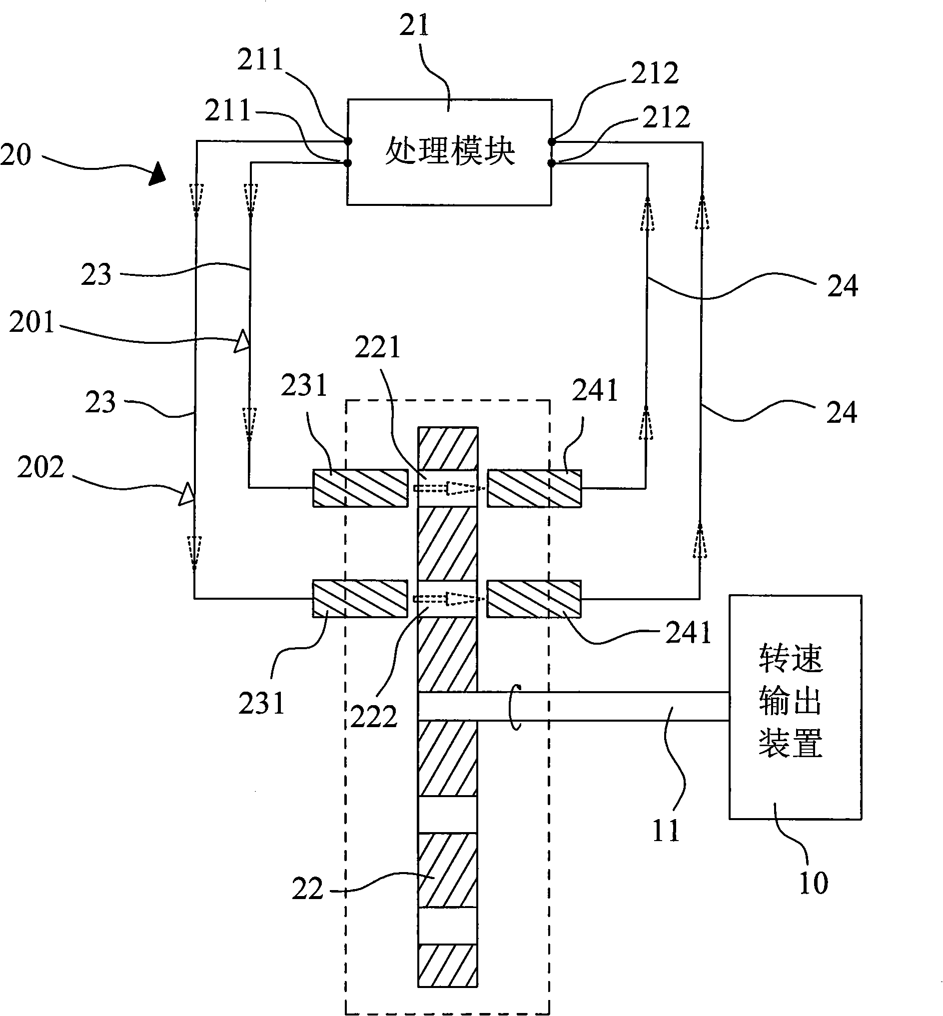
[0028] Please refer to figure 1 and figure 2 As shown, it shows the specific structure of a preferred embodiment of the present invention, including a rotational speed output device 10 and a passive rotational speed counter device 20. The rotational speed output device 10 uses its rotational speed output shaft 11 to output rotational kinetic energy. The passive rotational speed counter device 20 is used to detect the rotation of the rotational speed output shaft 11 to obtain real-time rotational characteristic data information of the rotational speed output device 10 .

[0029] Specifically, the passive tachometer device 20 of this embodiment includes a processing module 21 , a turntable 22 and two optical fiber transmission paths 201 and 202 . Wherein, the processing module 21 is used to process the optical signal received by the following receiving optical fiber 24 to calculate the rotational speed.

[0030] Each of the two optical fiber transmission paths 201 and 202 has...


PUM


Abstract

The invention relates to technology for the field of rotating speed counting equipment of rotating objects, in particular to a passive rotating speed counting device and a counting method thereof, which has the advantages that the rotating speed measurement is free from interference, high in measurement accuracy, passive and safer, and is suitable for rotating characteristic measurement under severe environments such as high temperature, low temperature, underwater, high electromagnetic interference and the like. The device comprises a processing device, an optical fiber transmission channel and a turntable, wherein the optical fiber transmission channel comprises a transmitting optical fiber and a receiving optical fiber; the transmitting optical fiber transmits an optical signal by a transmitting core wire; the receiving optical fiber receives the optical signal transmitted by the transmitting optical fiber by a receiving core wire; the turntable is arranged on a rotating speed output shaft of a rotating speed output device to be measured and is blocked on an optical path between the transmitting optical fiber and the receiving optical fiber; at least one group of through holes are arranged on the turntable; in the process of rotating the turntable, the through holes are intermittently connected with the optical path between the transmitting optical fiber and the receiving optical fiber; and the processing module is used for processing the optical signal received by the receiving optical fiber so as to calculate the rotating speed.

Description

technical field [0001] The invention relates to the technology in the field of rotational speed counting equipment for rotating objects, in particular to a passive rotational speed counting device and a counting method thereof with simple structure, safe use and wide application range. Background technique [0002] At present, the speed measurement and counting of rotating objects are basically realized by various speed sensors. There are many kinds of speed sensors and they are widely used. The reason is that various motors are widely used in automatic control systems and automatic instruments. There are strict requirements for the accurate measurement of low speed (such as less than one revolution per hour), high speed (such as hundreds of thousands of revolutions per minute), stable speed (such as the error is only a few ten thousandths) and instantaneous speed. [0003] Commonly used speed sensors include magnetoelectric induction type, photoelectric effect type, Hall ef...

Claims


Application Information

Patent Timeline
Patent Type & Authority Applications(China)
IPC IPC(8): G01P3/486
Inventor 吴文军唐晟
Owner SHENZHEN HWAYING CENTURY OPTOELECTRIC TECH CO LTD
Learn More