Method for improving tube bundle effect of heat transfer tube

A heat transfer tube and slot height technology, which is applied in the direction of tubular elements, heat exchange equipment, lighting and heating equipment, etc., to achieve the effect of improving the heat exchange performance and high heat exchange performance of the condensing side.

Active Publication Date: 2013-09-25
维联传热技术(上海)有限公司
View PDF2 Cites 0 Cited by
  • Summary
  • Abstract
  • Description
  • Claims
  • Application Information

AI Technical Summary

Problems solved by technology

So far, due to the lack of good research and analysis of the heat transfer heat of the refrigerant condensing outside the tube, the coolant (such as water) flows and exchanges heat in the tube, and the condensate of the heat transfer tube arranged in a certain order falls on the outer surface of the tube. The influence of accumulation on heat exchange, people have not been able to find out that the heat transfer tubes for the refrigerant condensing outside the tube and the heat transfer tube for the coolant (such as water) flowing in the tube and arranged in a certain order are well overcome and Specific methods to balance the defects of the above two casts

Method used

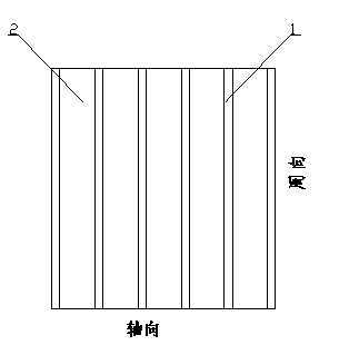
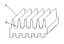
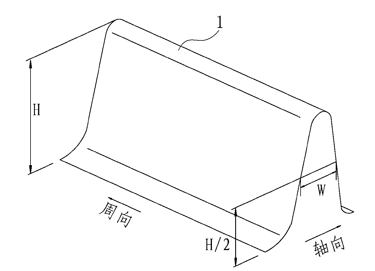

Image

  • Method for improving tube bundle effect of heat transfer tube
  • Method for improving tube bundle effect of heat transfer tube
  • Method for improving tube bundle effect of heat transfer tube

Examples


Embodiment 1

[0043] see image 3 , the heat transfer tube provided in this embodiment is based on the existing heat transfer tube, by using a thinner slotting tool to process fin grooves 304 on the top of part of the fins 301, and the fins 301 are formed along the circumferential direction There are inter-fin slots 302, and fin platforms 303 are formed between adjacent inclined slots.

[0044] In this embodiment, when the fin grooves are processed, a fin groove is formed every two smooth fins on the fins of the heat transfer tube.

[0045] Based on the above scheme, if it is assumed that the code name of the smooth fin without fin groove is "0", and the code name of the slotted fin with fin groove is "1", such as image 3 As shown, in this embodiment, the number of fin heads is 3, and there is a fin opening groove for every two smooth fins along the axial direction on the fin, and the "001001" type heat transfer tube can be processed. Obviously The ratio of smooth fins is 2 / 3.

[0046] ...

Embodiment 2

[0059] In the heat transfer tube provided in this embodiment, when the fin grooves are processed, two fin grooves are continuously formed on every two smooth fins on the fins of the heat transfer tube.

[0060] see Figure 4 , in the present embodiment, the number of fin heads is 4, and the fin grooves 304 are opened every two fins on the fin 301 in the axial direction, and the heat transfer tube of the "0011" type can be processed (K=1 / 2 ). And other structures are the same as the heat transfer tube provided in Embodiment 1, as mentioned above, and will not be repeated here.

Embodiment 3

[0062] In the heat transfer tube provided in this embodiment, when the fin grooves are processed, two fin grooves are continuously formed on every other smooth fin on the fins of the heat transfer tube.

[0063] see Figure 5 , in this embodiment, the number of fin heads is 3, and each fin opening groove 304 is spaced apart on the fin 301 in the axial direction, and the heat transfer tube of the "011011" type can be processed (K=1 / 3) . And other structures are the same as the heat transfer tube provided in Embodiment 1, as mentioned above, and will not be repeated here.


PUM


Abstract

The invention discloses a heat transfer tube for improving tube bundle effect. Smooth fins for increasing the heat exchange area are pressed on an outer surface of the heat transfer tube; fin grooves can be formed on the tops or side surfaces of partial smooth fins to form grooved fins; the smooth fins and the grooved fins are simultaneously formed on the heat transfer tube; and the ratio of the smooth fins to the grooved fins is determined by the row number of heat transfer tube bundles. In a larger tube bundle, the heat transfer tube can prevent the condensing side heat exchange performance from being greatly reduced due to a swamping effect, effectively maintains higher heat exchange performance, and also can avoid extra workload due to different heat exchange tubes in the whole heat exchanger. Meanwhile, compared with the prior art, in the larger tube bundle, the heat transfer tube has the condensing side heat exchange performance improved by 15 to 45.5 percent.

Description

technical field [0001] The invention belongs to the technical field of heat transfer equipment, and in particular relates to a heat transfer tube for condensation. Background technique [0002] In refrigeration and air conditioning and related industries, water-cooled condensers have been widely used. Most of them are shell-and-tube heat exchangers, in which the refrigerant condenses outside the tubes to exchange heat, and the coolant (such as water) flows inside the tubes to exchange heat. Because the thermal resistance of the refrigerant side accounts for the main part, it is necessary to adopt enhanced heat transfer technology on this side. For the phase change heat transfer of condensation, there are many heat transfer tubes specifically for this type of process: such as US Patent US5996686 and US Patent US5669441, It discloses a heat transfer tube for condensation-enhanced surface, which is formed into fins (two-dimensional heat transfer tube) on the outer surface of t...

Claims


Application Information

Patent Timeline
Patent Type & Authority Patents(China)
IPC IPC(8): F28F1/12F25B39/04
Inventor 罗忠邱亚林曹建英陆蛟
Owner 维联传热技术(上海)有限公司
Why Eureka
Try Eureka