Ion exchange equipment
An ion exchange and equipment technology, applied in the direction of ion exchange water/sewage treatment, etc., can solve the problems of incomplete transportation of failed resin fillers, long water production cycle, and high water production quality, so as to improve water production quality, reduce equipment cost, Improve the effect of water production cycle
- Summary
- Abstract
- Description
- Claims
- Application Information
AI Technical Summary
Problems solved by technology
Method used
Image
Examples
Embodiment 1
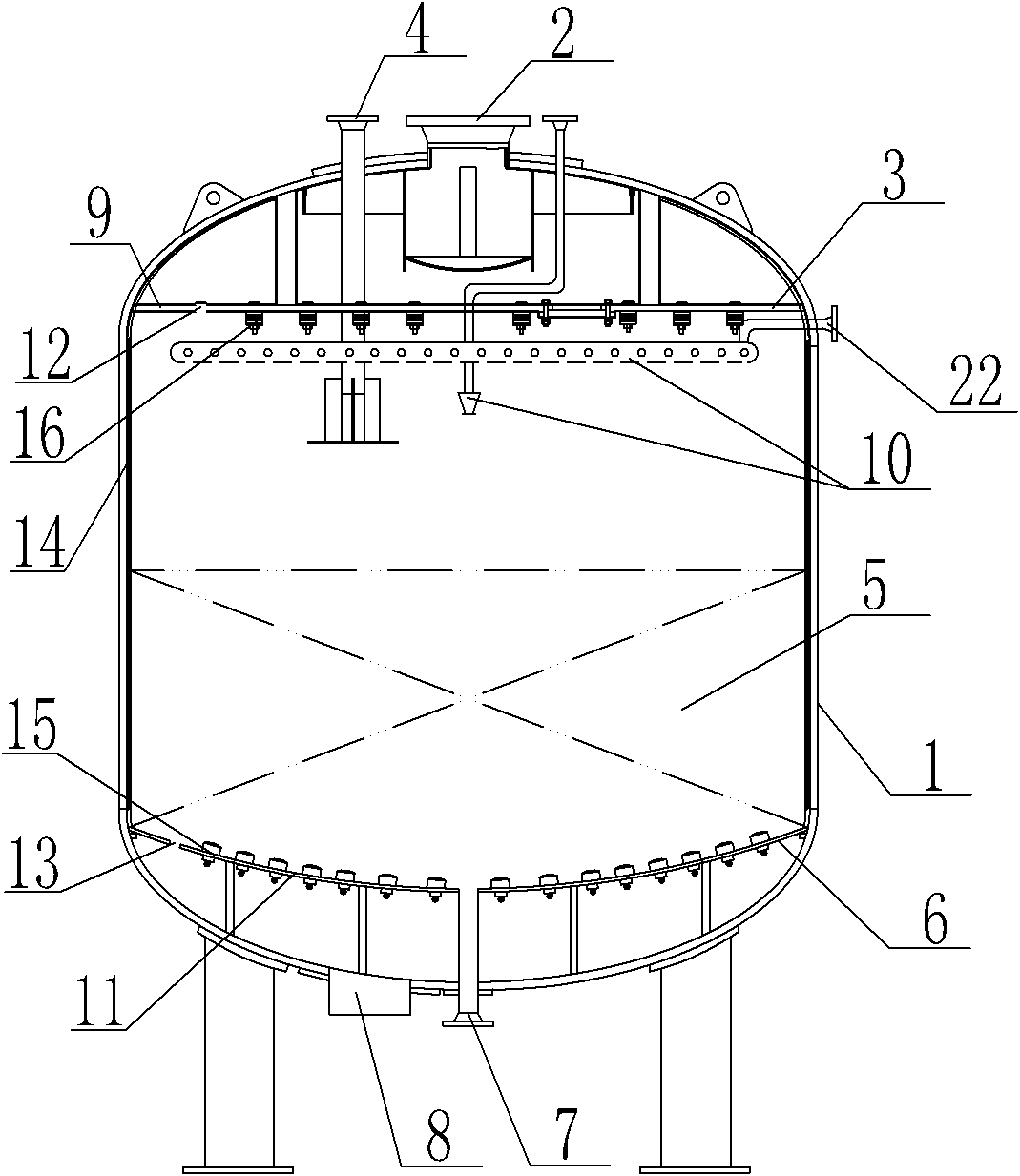
[0030] Embodiment 1 of the present invention: an ion exchange device, including a housing 1, a water inlet 2, a water distribution device 3, a grease inlet 4, a resin packing layer 5, a water collection device 6, a grease outlet 7 and a water outlet 8 , the water inlet 2 is located on the top of the housing 1, the water distribution device 3 is located on the upper part of the housing 1, the water distribution device 3 includes a water distribution plate 9 and a water distributor 16, and the water collecting device 6 is located at the top of the housing 1 At the bottom, the water collecting device 6 includes a water collecting plate 11 and a water collecting device 15, the resin filler layer 5 is arranged above the water collecting device 6, and the upper end of the grease outlet 7 is arranged at the central point of the water collecting device 6 and connected to the housing 1 The bottom of the housing 1 is also provided with a water outlet 8, and a spray device 10 is provided ...
Embodiment 2
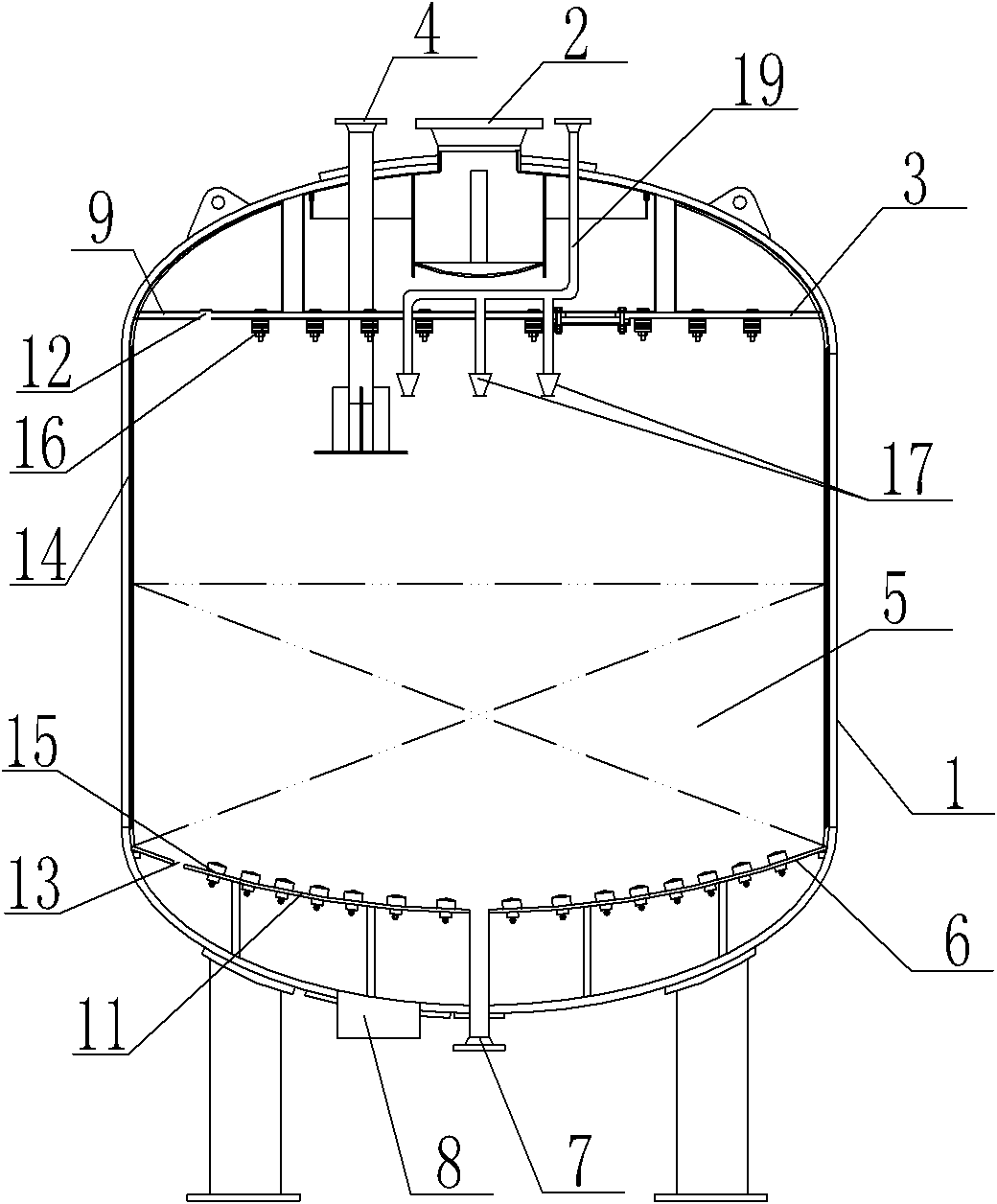
[0031]Embodiment 2 of the present invention: an ion exchange device, including a housing 1, a water inlet 2, a water distribution device 3, a grease inlet 4, a resin packing layer 5, a water collection device 6, a grease outlet 7 and a water outlet 8 , the water inlet 2 is located on the top of the housing 1, the water distribution device 3 is located on the upper part of the housing 1, the water distribution device 3 includes a water distribution plate 9 and a water distributor 16, and the water collecting device 6 is located at the top of the housing 1 At the bottom, the water collecting device 6 includes a water collecting plate 11 and a water collecting device 15, the resin filler layer 5 is arranged above the water collecting device 6, and the upper end of the grease outlet 7 is arranged at the central point of the water collecting device 6 and connected to the housing 1 The bottom of the housing 1 is also provided with a water outlet 8, and the bottom of the water distrib...
Embodiment 3
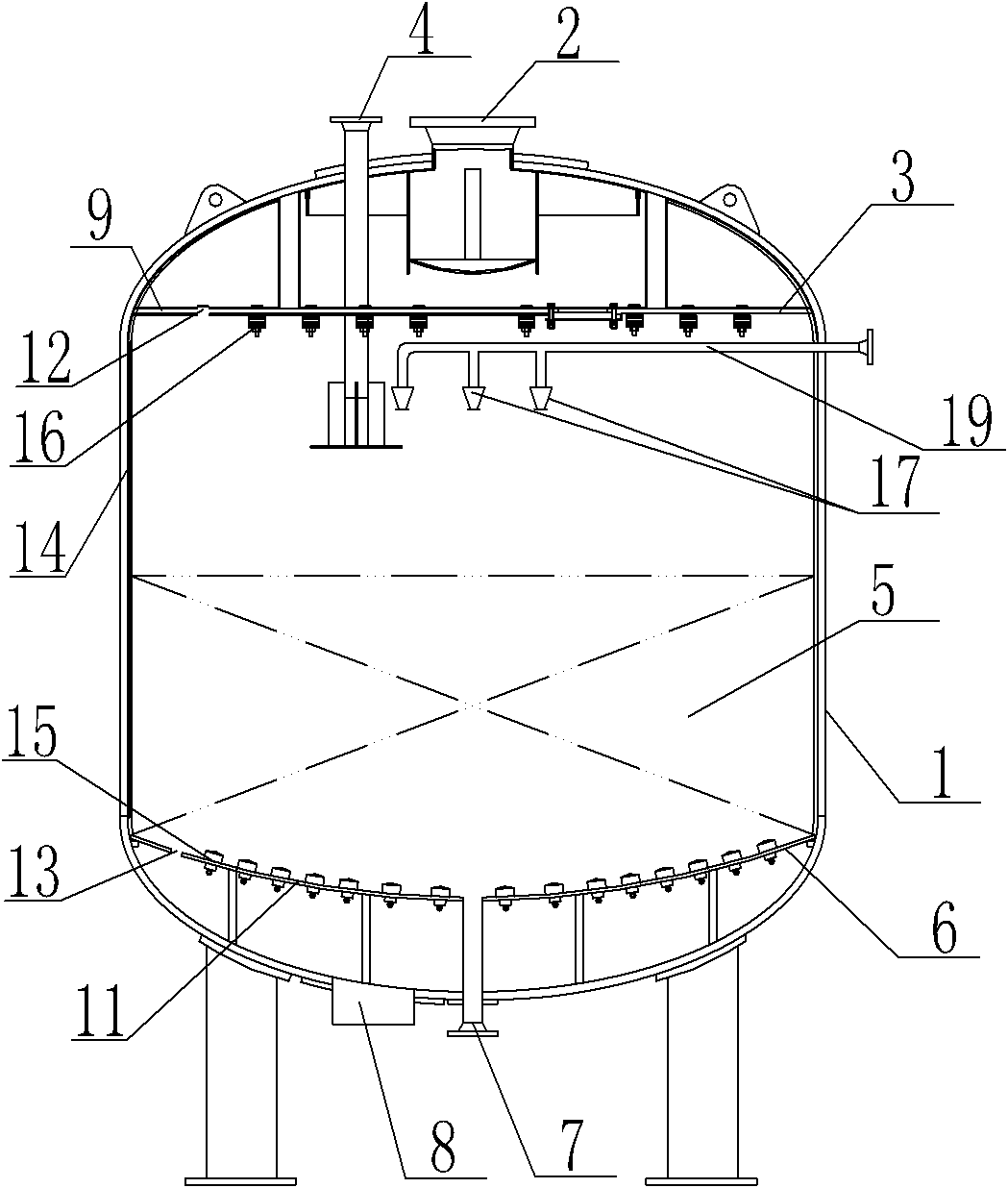
[0032] Embodiment 3 of the present invention: an ion exchange device, including a housing 1, a water inlet 2, a water distribution device 3, a grease inlet 4, a resin packing layer 5, a water collection device 6, a grease outlet 7 and a water outlet 8 , the water inlet 2 is located on the top of the housing 1, the water distribution device 3 is located on the upper part of the housing 1, the water distribution device 3 includes a water distribution plate 9 and a water distributor 16, and the water collecting device 6 is located at the top of the housing 1 At the bottom, the water collecting device 6 includes a water collecting plate 11 and a water collecting device 15, the resin filler layer 5 is arranged above the water collecting device 6, and the upper end of the grease outlet 7 is arranged at the central point of the water collecting device 6 and connected to the housing 1 The bottom of the housing 1 is also provided with a water outlet 8, and a spray device 10 is provided ...
PUM
| Property | Measurement | Unit |
|---|---|---|
| diameter | aaaaa | aaaaa |
| diameter | aaaaa | aaaaa |
| diameter | aaaaa | aaaaa |
Abstract
Description
Claims
Application Information
 - Generate Ideas
- Intellectual Property
- Life Sciences
- Materials
- Tech Scout
- Unparalleled Data Quality
- Higher Quality Content
- 60% Fewer Hallucinations
Browse by: Latest US Patents, China's latest patents, Technical Efficacy Thesaurus, Application Domain, Technology Topic, Popular Technical Reports.
© 2025 PatSnap. All rights reserved.Legal|Privacy policy|Modern Slavery Act Transparency Statement|Sitemap|About US| Contact US: help@patsnap.com


