
Limiting device for guide frame

A technology of limit device and guide frame, which is applied in the direction of lifting device and lifting frame, can solve the problems of low production efficiency, templates hitting people, and low safety factor, so as to achieve safety factor and production efficiency improvement, great economic benefits, cost-effective effect

Inactive Publication Date: 2011-04-06
SUZHOU XINXIELI MACHINE MFG
View PDF8 Cites 6 Cited by
  • Summary
  • Abstract
  • Description
  • Claims
  • Application Information

AI Technical Summary

Problems solved by technology

If the lifting frame cannot rise to the position, the template may roll out from the gap between the limit stop and the lifting frame, causing damage to the slab, and it is more likely that the template will hit people
[0003] Problems such as low production efficiency and low safety factor caused by the operation stoppage, jamming, and inaccurate stop positioning of the original equipment lifting frame have become problems that need to be solved urgently in the industry

Method used


Image

  • Limiting device for guide frame
  • Limiting device for guide frame

Examples


Embodiment Construction

[0017] The present invention will be further described below in conjunction with the accompanying drawings and specific embodiments.

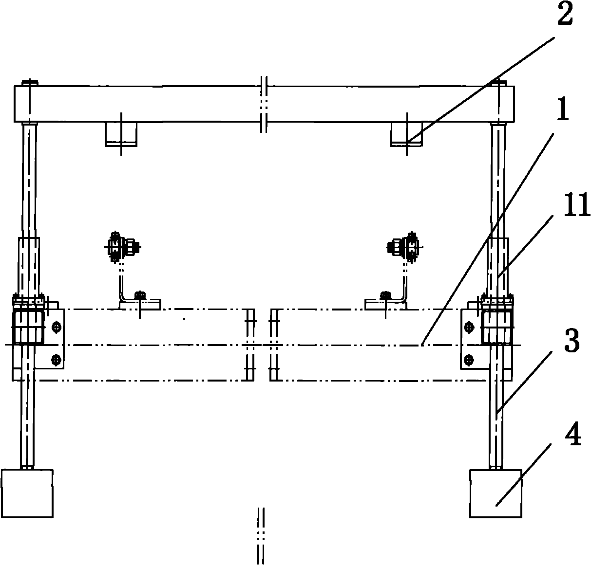
[0018] Such as figure 1 A guide frame limiting device shown is used for guiding and limiting the lifting frame. The guide frame limiting device is composed of four parts: the lifting frame 1, the limit stopper 2, the guide shaft 3 and the counterweight 4. Wherein the limit block 2 is located at the top of the guide frame device, the two sides of the guide frame limit device are two symmetrical guide shafts 3 in the vertical direction, and the bottom ends on both sides of the two guide frame limit devices are provided with two The counterweight 4, the lifting frame 1 and the guide shaft 3 are connected through a linear bearing 11.

[0019] Lifting frame 1 is inserted in the installation hole of counterweight 4 centers, and linear bearing 11 is stuck on the guide shaft 3, and linear bearing 11 is connected with lifting frame by screw.

[0020] ...


PUM


Abstract

The invention discloses a limiting device for a guide frame, which is used for guiding and limiting a crane. The limiting device for the guide frame consists of the crane, a limit stop, guiding shafts and balance weight blocks, wherein the limit stop is positioned at the topmost end of the guide frame device; the two symmetrical guiding shafts in a vertical direction are arranged on two sides of the limiting device for the guide frame; two balance weight blocks are arranged at the bottom of the two sides of the two limiting devices for the guide frame; and the crane is connected with the guiding shafts through a linear bearing. The device has the advantages that: the problems of guiding and limiting function of the crane are solved effectively; the safety factor is greatly increased; continuous and stable production is ensured; and the device has a simple structure and is easy to manufacture.

Description

technical field [0001] The invention relates to the technical field of machinery, in particular to a guide frame limiting device used for guiding and limiting a lifting frame. Background technique [0002] The guide part of the original equipment is not a linear bearing, but a guide sleeve (which is relatively difficult to process). During the lifting process of the lifting frame, the guide shaft and the guide sleeve are in contact with the entire surface, plus processing and installation reasons (both It is necessary to ensure concentricity and verticality), which greatly increases the occurrence of pauses and stagnation. If the lifting frame cannot rise to the position, the template may roll out from the gap between the limit stop and the lifting frame, causing damage to the slab, and it is more likely that the template will hit people. [0003] Problems such as low production efficiency and low safety factor caused by the original equipment lifting frame running stop, ja...

Claims


Application Information

Patent Timeline
Patent Type & Authority Applications(China)
IPC IPC(8): B66F7/28
Inventor 王辉
Owner SUZHOU XINXIELI MACHINE MFG
Learn More