
Carbon/carbon composite material lifting appliance for high-temperature furnace

A carbon composite material, high temperature furnace technology, applied in the direction of load hanging components, transportation and packaging, can solve the problems of harsh working conditions and poor safety, achieve a wide range of applications, low manufacturing costs, and avoid harsh conditions in high temperature furnaces Effect

Active Publication Date: 2011-04-06
XIAN CHAOMA SCI TECH
View PDF4 Cites 8 Cited by
  • Summary
  • Abstract
  • Description
  • Claims
  • Application Information

AI Technical Summary

Problems solved by technology

[0003] The technical problem to be solved by the present invention is to provide a carbon / carbon composite material spreader for high-temperature furnaces in view of the deficiencies in the above-mentioned prior art, which has a simple structure, convenient assembly, easy operation and good use effect, and safe and reliable working performance , Long service life, can effectively solve the problem that existing high-temperature furnace spreaders cannot go through the high-temperature treatment process of 1500 ℃ ~ 3000 ℃ together with the processed products, operators need to go down to the furnace to lift products, poor working conditions, Extremely poor security and other issues

Method used


Image

  • Carbon/carbon composite material lifting appliance for high-temperature furnace
  • Carbon/carbon composite material lifting appliance for high-temperature furnace
  • Carbon/carbon composite material lifting appliance for high-temperature furnace

Examples


Embodiment Construction

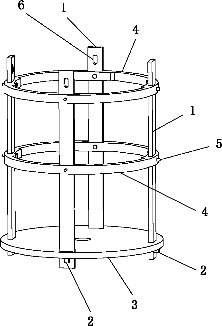
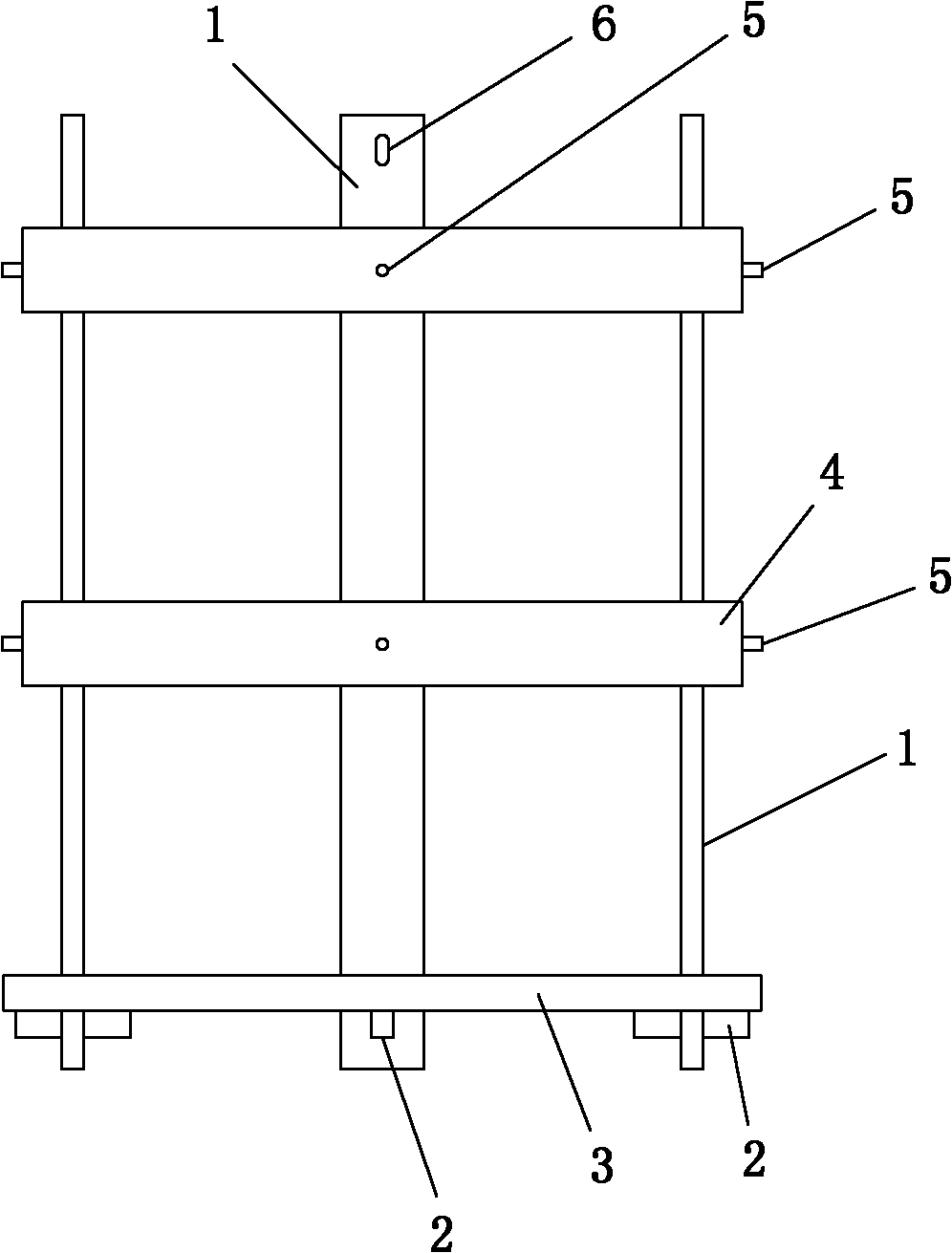
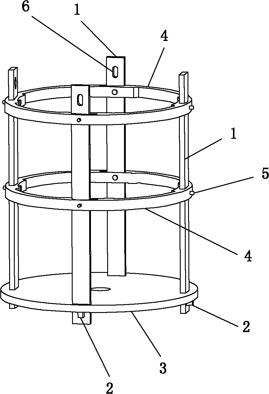
[0028] Such as figure 1 , figure 2 As shown, the present invention includes a load-bearing chassis 3 for containing processed products, a plurality of load-bearing suspenders 1 arranged vertically on the load-bearing chassis 3 evenly along the circumferential direction, and multiple channels for multiple An annular ring plate 4 that is fixed to the load-bearing suspenders 1 and is arranged horizontally. The suspenders 1 are fastened and connected by a fastening device 1, and the bottoms of the multiple load-bearing suspenders 1 are fixedly installed on the load-bearing chassis 3, and the load-bearing chassis 3 is correspondingly provided with a plurality of for the described The mounting holes for the load-bearing suspenders 1 are installed, and the load-bearing chassis 3 and the multiple load-bearing suspenders 1 are fastened and fixed by the fastening device 2. The structure and structure of the multiple load-bearing suspenders 1 All are the same size. The plurality of r...


PUM

PropertyMeasurementUnit
Densityaaaaaaaaaa
Tensile strengthaaaaaaaaaa
Densityaaaaaaaaaa

Abstract

The invention discloses a carbon / carbon composite material lifting appliance for a high-temperature furnace, which comprises a bearing chassis, a plurality of borne lifting rods and a plurality of annular plates, wherein the borne lifting rods are distributed on the bearing chassis along the circumference direction; the annular plates are respectively used for fixing the borne lifting rods and are distributed in the horizontal direction; the annular plates and the bearing chassis are firmly connected with the borne lifting rods respectively by a fastening device I and a fastening device II; and the borne lifting rods, the bearing chassis, the annular plates, the fastening device I and the fastening device II are made of a carbon / carbon composite material and commonly form an integral type lifting appliance which can carry out heat treatment with a treated product under the temperature condition of 1,500-3,000 DEG C. The invention has the advantages of simple structure, good use effect, safe and reliable working performance and long service life, is convenient for assembly and simple and convenient for operation, and can solve the problems that the traditional lifting appliance for a high-temperature furnace can not be subjected to high-temperature treatment process together with the treated product and needs an operator to lift the product in the furnace, the labor condition is poor, the safety is low, and the like.

Description

technical field [0001] The invention belongs to the technical field of high-temperature treatment production process equipment for carbon / carbon composite materials and graphite materials, and in particular relates to a carbon / carbon composite material hanger for high-temperature furnaces. Background technique [0002] At present, when preparing carbon / carbon composite materials, graphite materials, etc., the working temperature of the high-temperature treatment furnace used is mostly in the range of 1500°C to 3000°C. There is no special high-temperature-resistant hanger when the products are loaded out of the furnace, and ordinary steel can only be used first. Lift the product into the furnace with a spreader, and then the operator goes into the furnace to unload the product, and then lifts the spreader out of the furnace; when the furnace is released, the operator also needs to go down into the furnace to load the product into the spreader and lift it out of the furnace. H...

Claims


Application Information

Patent Timeline
IPC IPC(8): B66C1/22
Inventor 苏君明肖志超谢英姿胡振英邢如鹏
Owner XIAN CHAOMA SCI TECH
Learn More