
Ring spinning machine

A ring spinning machine and machine technology, applied in spinning machines, continuous winding spinning machines, textiles and papermaking, etc., can solve the problems of high structural cost, etc., and achieve the effect of small size and small friction loss

Active Publication Date: 2014-09-10
SAURER GERMANY GMBH & CO KG
View PDF9 Cites 0 Cited by
  • Summary
  • Abstract
  • Description
  • Claims
  • Application Information

AI Technical Summary

Problems solved by technology

By arranging an additional extraction device of this type at each station it is possible to ensure that there is always a sufficiently high vacuum at each station, but the necessary structural outlay is considerable and in ring spindles with several spinning stations barely affordable in spinning machines

Method used


Image

  • Ring spinning machine
  • Ring spinning machine
  • Ring spinning machine

Examples


Embodiment Construction

[0051] figure 1 A front view of a ring spinning machine 1 constructed in accordance with the present invention with an extraction device 9 is shown. As shown in the figure, this type of ring spinning machine 1 has a large number of machine sections 4 between the end frames 2 and 3, for example 25 or more. This type of machine section 4 has a large number (for example, 50) spinning stations, of which 25 spinning stations are arranged in figure 1 On the front side of the ring spinning machine 1 shown, 25 spinning stations are arranged on the rear side of the machine.

[0052] And as figure 1 As shown schematically, this type of textile machine is equipped with a drafting device 5, and the drafting rollers 6, 7, 8 of the drafting device 5 are usually arranged on both longitudinal sides of the machine along the length of the machine. The extraction device 9 is installed under the drawing roller 8 of the drafting device 5. The yarn lifting tube 10 of the extraction device 9 is connect...


PUM


Abstract

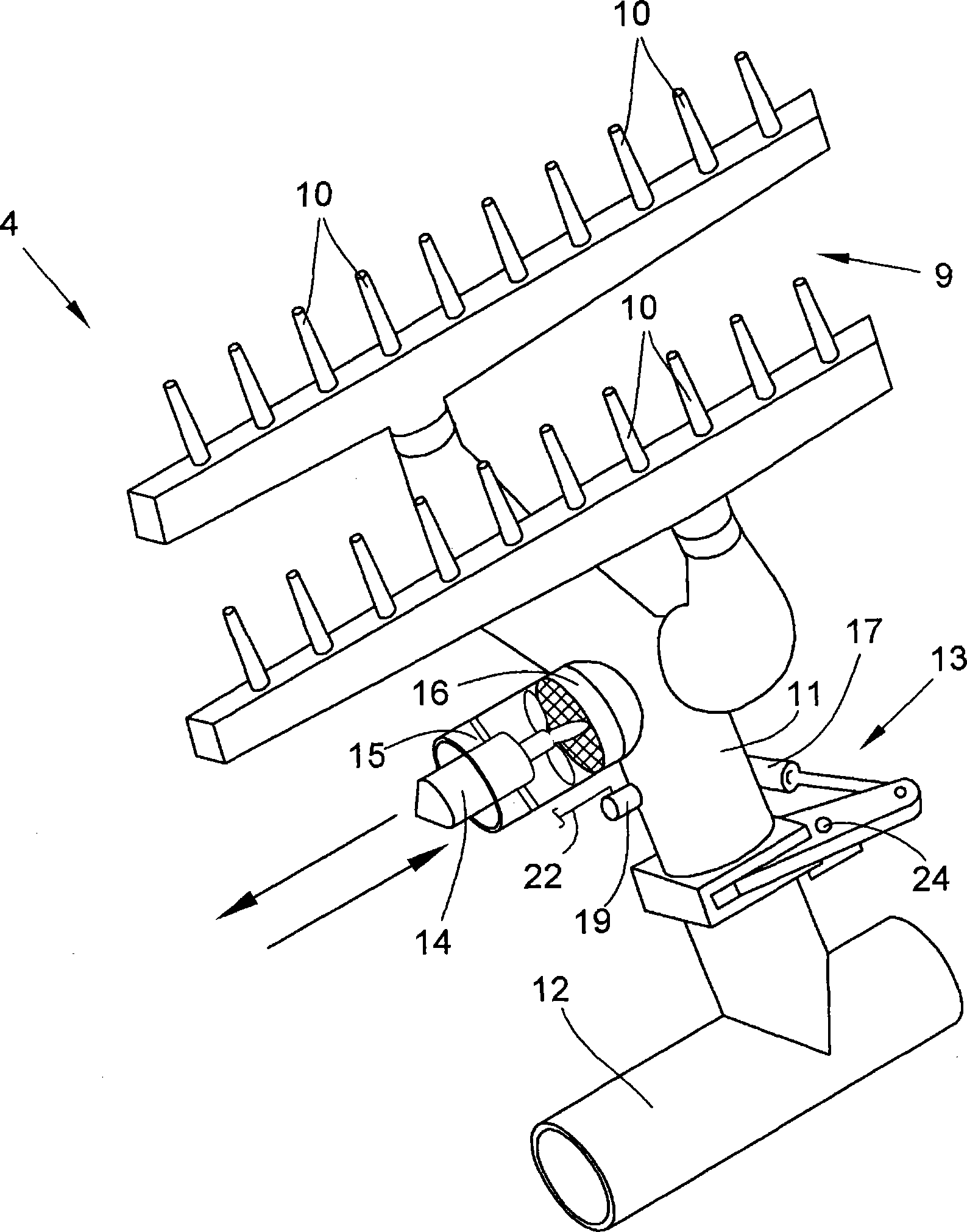
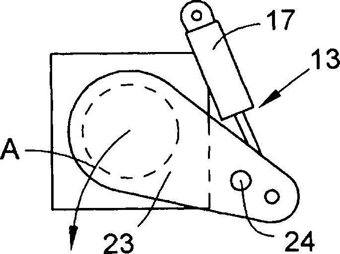
The machine (1) has section-wise arranged spinning areas positioned next to each other on both sides of a machine longitudinal axis. Each area has suction pipes (10) in an area of a stretching unit arrangement (5) attached at a negative pressure-subjectable filter device (20) by a suction channel (12). The pipes are connected to a negative pressure source i.e. electric motor driven ventilator, or the channel by actuating a defined controllable slider element (13) that is engaged into a channel part (11), where the negative pressure source is arranged at the channel part. USE : Ring spinning machine for use in a textile industry. ADVANTAGE : The pipes are connected to the negative pressure source or the channel by actuating the defined controllable slider element that is engaged into the channel part, so that the driving power required for producing sufficient high negative pressure in the area of the pipes is optimized and friction losses of the negative pressure stream are reduced, thus reducing constructional and financial cost of the spinning machine. DESCRIPTION OF DRAWINGS : The drawing shows a schematic front view of a ring spinning machine with suction devices that are arranged below a stretching unit arrangement. 1 : Ring spinning machine 5 : Stretching unit arrangement 10 : Suction pipes 11 : Channel part 12 : Suction channel 13 : Defined controllable slider element 20 : Negative pressure-subjectable filter device.

Description

Technical field [0001] The present invention relates to a ring spinning machine, wherein the ring spinning machine has a large number of spinning stations arranged in sections and positioned adjacent to each other on both sides of the longitudinal axis of the machine, and each having An extraction tube located in the area of ​​the drafting device, which is connected via an extraction channel to a filter device capable of being loaded with negative pressure. Background technique [0002] This type of ring spinning machine has long been known in the textile industry and is sometimes described in detail in various patent specifications. [0003] German utility model DE-GM8512843 or DE10139077A1 describes, for example, a ring spinning machine, which in all cases has a drafting device located in the area of ​​their numerous spinning stations and where the drafting The extraction device below the device. The extraction device used not only to handle dust and fiber fly, but also in the ...

Claims


Application Information

Patent Timeline
Patent Type & Authority Patents(China)
IPC IPC(8): D01H5/66D01H5/68D01H11/00
CPCD01H11/00D01H5/66D01H1/162
Inventor 彼得·曼恩
Owner SAURER GERMANY GMBH & CO KG
Learn More