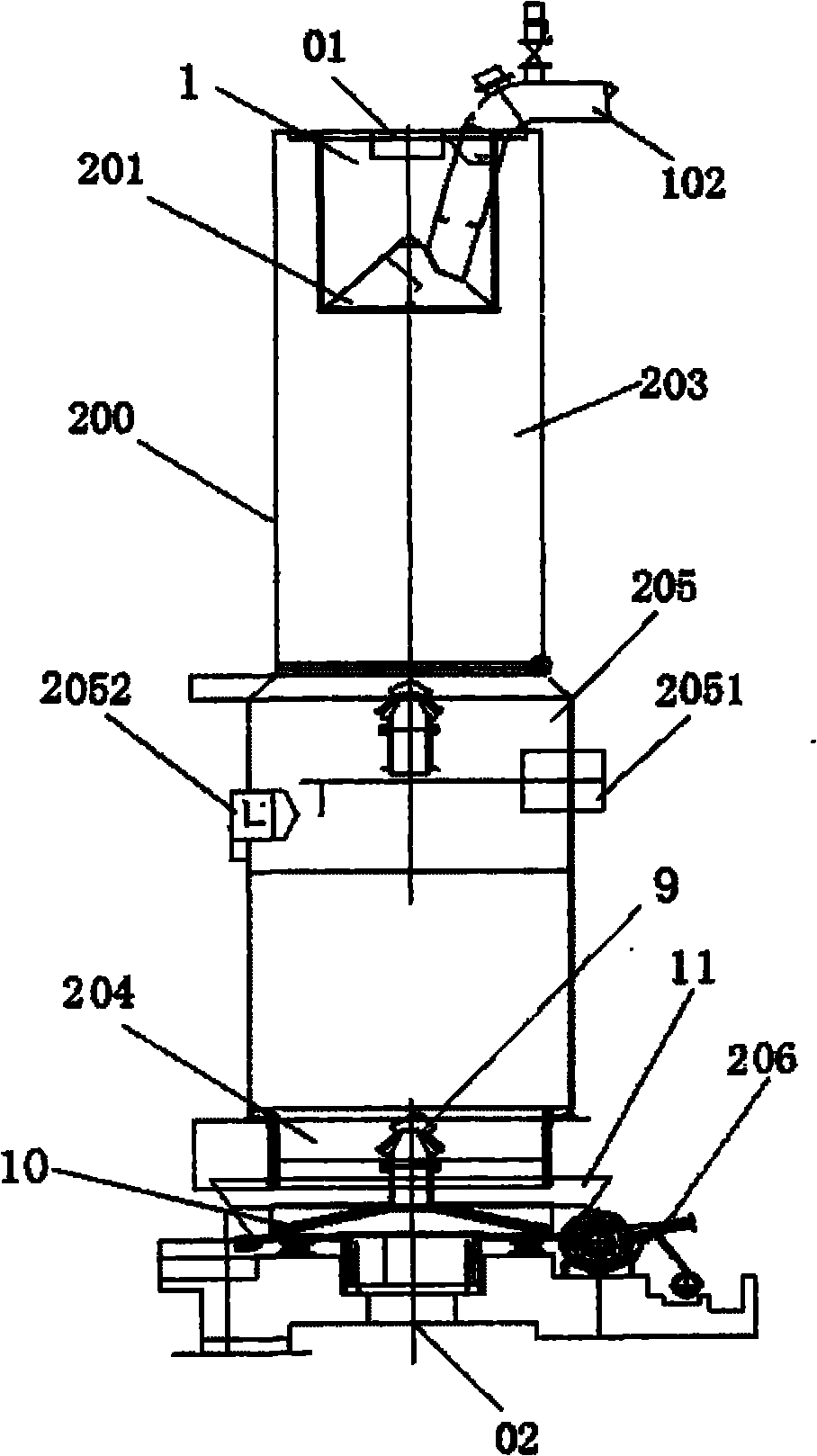
Oil shale oven and carbonification process
A technology for oil shale and dry distillation furnace, applied in the field of dry distillation furnace, can solve the problems of unsatisfactory dry distillation effect, waste of raw materials, incomplete dry distillation, etc., and achieve the effects of reducing the temperature difference of the dry distillation layer, less environmental pollution, and convenient operation.
- Summary
- Abstract
- Description
- Claims
- Application Information
AI Technical Summary
Problems solved by technology
Method used
Image
Examples
Embodiment 1
[0047] see figure 1 , the cylindrical structure shown in the figure is 3600mm-3800mm in diameter, and the retort furnace body is divided into upper, middle and lower sections. Into hot cycle gas.
[0048] The Huadianyuan furnace includes a furnace body 200, which is provided with a raw material inlet 01, a gas collection umbrella 201, an oil gas outlet 102, a dry distillation section 203, a cooling section 204, and a mixing chamber 205. The ash discharge transmission device 206, the main air inlet 02 is set at the center of the bottom of the furnace body 200;
[0049] The mixing chamber 205 is provided with gas inlets 2051 and 2052 for a central heat cycle.
[0050] As well as the ash discharge device 10 and the ash container 11 for processing the dust after carbonization, the gas collection umbrella 201 is arranged inside the furnace body 200 , and the ash discharge device 10 and the ash container 11 are installed at the bottom of the furnace body 200 . The dry distillatio...
Embodiment 2
[0061] see figure 2 , it includes a furnace body 2, an ore storage bin 21 on the top of the furnace body 2 is set, a raw material inlet 20 is arranged in the center of the ore storage bin 21, and the right side of the raw material inlet 20 is an oil and gas outlet 210; below the dry distillation section 23 is a mixing Chamber 221, the upper side of the mixing chamber 221 is provided with two primary central thermal cycle gas inlets 24, 25, the lower side is provided with two secondary central thermal cycle gas inlets 26, 27, and the bottom of the furnace body 2 is also provided with an ash discharge transmission device 29. The main air inlet 28 is located at the center of the bottom of the furnace body 2 .
[0062] The sieved oil shale with a particle size of 8-40 mm first enters the ore storage bin 21 on the top of the carbonization furnace, and enters the furnace through the double-bell intermittent distribution equipment. The oil shale entering the carbonization furnace f...
Embodiment 3
[0074] see image 3 , which includes a furnace body 3, a dry distillation section 31, a cooling section 32, and a mixing chamber 33, and an oil and gas outlet 35 is arranged at the upper right corner of the dry distillation section 31;
[0075] The lower part of the furnace body 3 is provided with an ash discharge device 37 and an ash pan 38 for processing the dust after carbonization, and a main air inlet 36 is provided at the center of the bottom of the furnace body;
[0076] First, the 4-15mm granular shale enters the retort section 31 and is heated by the circulating gas at 650-750°C entering horizontally. The retort section 31 is provided with an oil and gas outlet 35. When it reaches the bottom of the retort section 31, the shale on the high temperature side can reach 550°C. -600°C, the low temperature side is around 400°C, which has reached the dry distillation temperature. The dry-distilled shale semi-coke enters the mixing chamber 33 through air sealing, and the low-...
PUM
| Property | Measurement | Unit |
|---|---|---|
| Granularity | aaaaa | aaaaa |
| Granularity | aaaaa | aaaaa |
Abstract
Description
Claims
Application Information
 - R&D
- Intellectual Property
- Life Sciences
- Materials
- Tech Scout
- Unparalleled Data Quality
- Higher Quality Content
- 60% Fewer Hallucinations
Browse by: Latest US Patents, China's latest patents, Technical Efficacy Thesaurus, Application Domain, Technology Topic, Popular Technical Reports.
© 2025 PatSnap. All rights reserved.Legal|Privacy policy|Modern Slavery Act Transparency Statement|Sitemap|About US| Contact US: help@patsnap.com


