Soldering process of micro motor rotor commutator and pressure-sensitive sheet

A technology of micro motors and commutators, which is applied in the direction of manufacturing tools, welding equipment, metal processing equipment, etc., can solve the problems of large tin consumption, increased time and workload, etc., and achieve cost saving, manpower and material resources saving, and process structure The effect of simplification

Inactive Publication Date: 2012-11-14
深圳市天豪机电科技有限公司
View PDF0 Cites 0 Cited by
  • Summary
  • Abstract
  • Description
  • Claims
  • Application Information

AI Technical Summary

Problems solved by technology

[0002] The products put into use now include automatic tin wire feeding mechanism, rotor pressing mechanism, electric soldering iron welding mechanism, rotor positioning and rotating mechanism. During the welding process, because the temperature of the welding commutator wire leg is higher than that of welding the pressure sensitive sheet, Therefore, the two steps must be completed separately. First, the rotor commutator wire pins must be welded, and then the pressure-sensitive sheet should be installed, and then the pressure-sensitive sheet should be soldered. It is not possible to use one machine to complete the two welding steps. A machine is required. One machine solders the wires of the commutator, and two machines solder the pressure-sensitive sheet. Twice soldering increases the time and workload of this process, and at the same time consumes a lot of tin

Method used


Image

  • Soldering process of micro motor rotor commutator and pressure-sensitive sheet
  • Soldering process of micro motor rotor commutator and pressure-sensitive sheet

Examples


Embodiment Construction

[0016] In order to make the object, technical solution and advantages of the present invention clearer, the present invention will be further described in detail below in conjunction with the accompanying drawings and embodiments. It should be understood that the specific embodiments described here are only used to explain the present invention, not to limit the present invention.

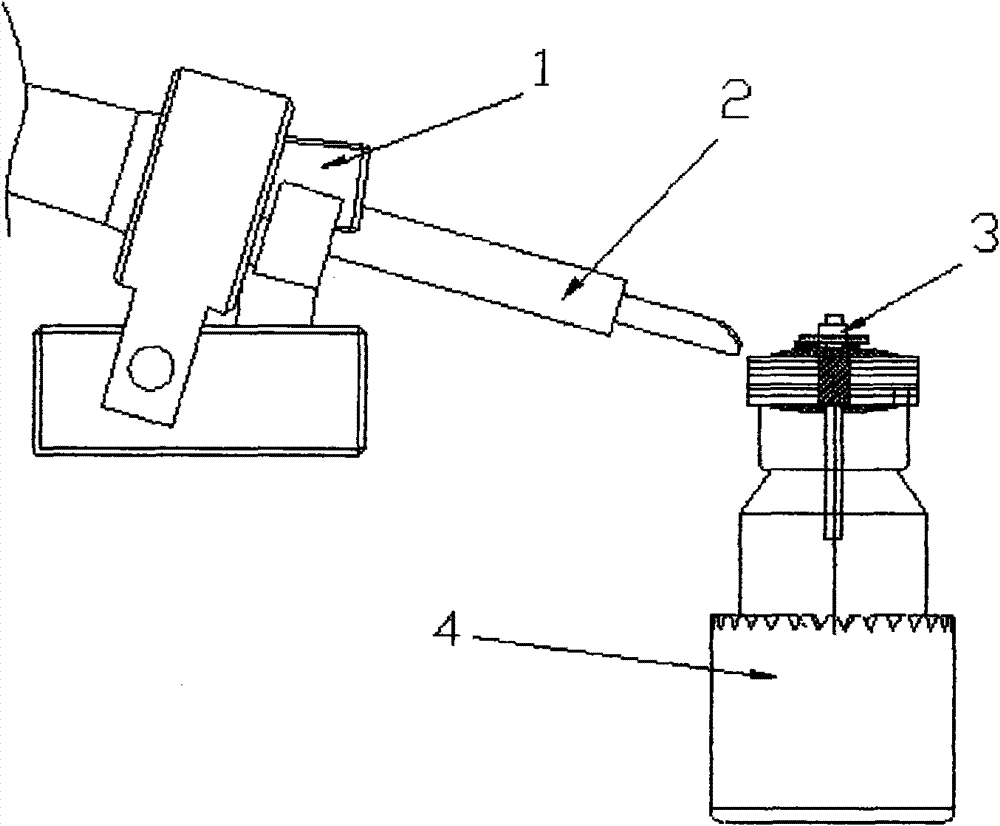
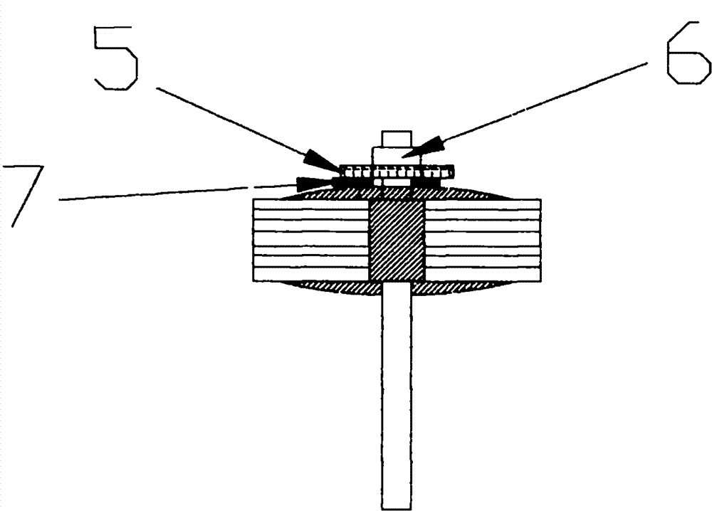
[0017] For the improvement of the welding process, it is characterized in that the original electric soldering iron welding mechanism 1, according to the required working process requirements, is improved to be able to complete the movement of two different distances in two steps, because the commutator pin 7 and The position of the pressure-sensitive sheet 6 is different, and the requirements for the welding temperature are different. The standard welding temperature of the commutator is 200-300°C higher than the standard temperature of the pressure-sensitive sheet 6. In the previous soldering proc...


PUM


Abstract

The invention discloses a welding process of a commutator architrave and a pressure-sensitive sheet, which is characterized in that: a soldering iron welding joint advances for the first time along a work thread, stops when advancing to a position above the commutator architrave, keeps 0.3mm away from the edge of the pressure-sensitive sheet, and is pressed downward to firmly weld an enameled wire and the commutator architrave, so that the welding of the commutator architrave is finished; and the soldering iron welding joint advances for the second time to the edge of a silver coating of the pressure-sensitive sheet or a position close to the silver coating, and quickly retreats after contacting the silver coating of the pressure-sensitive sheet. The improved process is to divide the advance of a soldering iron welding device into two stages so as to finish the welding process which is divided into two steps previously, so that the process is simple and quick and meets the process requirement of welding the architrave and the pressure-sensitive sheet; meanwhile, a process structure is simplified, and manpower, material resources and cost are saved.

Description

【Technical field】 [0001] The invention relates to the field of micro-motor welding technology, in particular to a welding technology that needs to weld wire feet and pressure-sensitive parts of a rotor commutator. 【Background technique】 [0002] The products put into use now include automatic tin wire feeding mechanism, rotor pressing mechanism, electric soldering iron welding mechanism, rotor positioning and rotating mechanism. During the welding process, because the temperature of the welding commutator wire leg is higher than that of welding the pressure sensitive sheet, Therefore, the two steps must be completed separately. First, the rotor commutator wire pins must be welded, and then the pressure-sensitive sheet should be installed, and then the pressure-sensitive sheet should be soldered. It is not possible to use one machine to complete the two welding steps. A machine is required. One machine solders the wires of the commutator, and two machines solder the pressure-...

Claims


Application Information

Patent Timeline
Patent Type & Authority Patents(China)
IPC IPC(8): B23K1/00
Inventor 雷云
Owner 深圳市天豪机电科技有限公司
Why Eureka
Try Eureka