
Method for preventing peritectic steel continuous casting blank from generating cracks

A technology for continuous casting slabs and cracks, which is applied in the field of preventing cracks in peritectic steel continuous casting slabs. It can solve the problems of deteriorating casting slab lubrication, reducing casting speed, and difficult gaps, so as to improve the quality of casting slabs and increase production efficiency. , the effect of reducing the amount of cleaning

Inactive Publication Date: 2011-03-30
ANGANG STEEL CO LTD
View PDF4 Cites 22 Cited by
  • Summary
  • Abstract
  • Description
  • Claims
  • Application Information

AI Technical Summary

Problems solved by technology

However, when the alkalinity of the mold slag is too high, it becomes very important and difficult to ensure that the mold slag is evenly filled into the gap between the slab and the mold. Bonding and breakout forced continuous casting production to re-adopt the technical route of reducing casting speed
How to coordinate the ratio of glass body and crystal body, and realize slow cooling and lubrication at the same time, this has not been properly solved in many continuous casting productions at home and abroad

Method used


Image

  • Method for preventing peritectic steel continuous casting blank from generating cracks
  • Method for preventing peritectic steel continuous casting blank from generating cracks
  • Method for preventing peritectic steel continuous casting blank from generating cracks

Examples


Embodiment 1

[0028] The composition and physical properties of the mold flux used in this example are shown in Table 1 and Table 2.

[0029] Table 1 Example 1 mold flux composition and physical properties (wt%)

[0030]

[0031] Table 2 Physical properties of mold flux in Example 1

[0032]

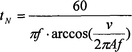
[0033] Process parameters: casting speed: 2.2m / min; slab size: 1050*135mm; water flow density at the wide side of the mold 4300l / min; water flow density at the narrow side of the mold 330l / min; the mold adopts sinusoidal vibration: the amplitude is 6.5mm, Vibration frequency is 196min -1 , Negative slip time 0.075s.

[0034] No obvious cracks were found on the surface of the slab produced by the continuous casting method of Example 1.

Embodiment 2

[0036] The composition and physical properties of the mold flux used in this example are shown in Table 3 and Table 4.

[0037] Table 3 Example 2 mold flux composition (wt%)

[0038]

[0039] Table 4 Physical properties of mold flux in Example 2

[0040]

[0041] Process parameters: casting speed: 2.1m / min; slab size: 1050*135mm; water flow density on the wide side of the mold 4400l / min; water flow density on the narrow side of the mold 340l / min; the mold adopts sinusoidal vibration: the amplitude is 7.4mm, Vibration frequency is 189min -1 , Negative slip time 0.16s.

[0042] No obvious cracks were found on the surface of the slab produced by the continuous casting method of Example 2.

Embodiment 3

[0044] The composition and physical properties of the mold flux used in this example are shown in Table 5 and Table 6.

[0045] Table 5 Example 3 mold flux composition (wt%)

[0046]

[0047] Table 6 Physical properties of mold flux in Example 3

[0048]

[0049] Process parameters: casting speed: 2.4m / min; slab size: 1050*135mm; water flow density at the wide side of the mold 4500l / min; water flow density at the narrow side of the mold 350l / min; the mold adopts sinusoidal vibration: the amplitude is 8.0mm, Vibration frequency is 150min -1 , Negative slip time 0.10s.

[0050] No obvious cracks were found on the surface of the slab produced by the continuous casting method of Example 3.

[0051] The off-line cleaning rate of peritectic steel in each embodiment is shown in Table 7, which is reduced from the original 3% to about 1%.

[0052] Table 7 embodiment off-line cleaning rate

[0053]


PUM

PropertyMeasurementUnit
Viscosityaaaaaaaaaa

Abstract

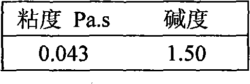
The invention discloses a method for preventing a peritectic steel continuous casting blank from generating cracks, which comprises a step of continuously casting by using a continuous casting machine. The method is characterized in that: in the continuous casting process, protective slag of which the alkalinity is 1.3 to 1.5 and the viscosity is 0.03 to 0.07Pa.s at 1,300 DEG C; a crystallizer adopts sinusoidal vibration, and has the vibration frequency of 150 to 198min<-1> and the vibration amplitude of 5.0 to 8.0mm; and the water volume of the crystallizer is reduced by 5 to 10 percent. The method effectively solves the problem of cracks on the surface of the peritectic steel continuous casting blank, improves the quality of the casting blank, and reduces casting blank clearing quantity and waste quantity.

Description

technical field [0001] The invention belongs to the method for improving the quality of cast slabs in the technical field of continuous casting, and in particular relates to a method for preventing cracks in peritectic steel continuous casting slabs. Background technique [0002] Steel with carbon content of 0.08% to 0.17% is called peritectic steel, which is very prone to cracks during continuous casting. The main reasons for crack sensitivity of peritectic steel are: [0003] When the peritectic steel is solidified, it is in the peritectic region (L+δ→γ), and the δ Fe → γ Fe phase transition, resulting in a larger volume shrinkage (0.38%). The solidified billet shell separates from the mold copper plate to form an air gap, which reduces the heat transfer rate from the billet shell to the mold, and the billet shell will become thinner and form a depression on the surface. Due to the uneven thickness of the billet shell, under the action of thermal stress, friction force...

Claims


Application Information

Patent Timeline
IPC IPC(8): B22D11/18B22D11/111B22D11/114
Inventor 张维维赵成林李德刚吕春风王丽娟李广帮
Owner ANGANG STEEL CO LTD
Learn More