
Pre-coding method for multi-user MIMO system

A precoding, multi-user technology, applied in the field of low-complexity precoding of multi-user MIMO systems, can solve the problem of high computational complexity

Inactive Publication Date: 2011-03-09
BEIJING UNIV OF POSTS & TELECOMM
View PDF3 Cites 38 Cited by
  • Summary
  • Abstract
  • Description
  • Claims
  • Application Information

AI Technical Summary

Problems solved by technology

[0005] The technical problem to be solved by the present invention is how to provide a low-complexity precoding method for MU-MIMO systems to solve the problem of high computational complexity of MSLNR technology, thereby reducing the operational complexity of the base station

Method used


Image

  • Pre-coding method for multi-user MIMO system
  • Pre-coding method for multi-user MIMO system
  • Pre-coding method for multi-user MIMO system

Examples


Embodiment 1

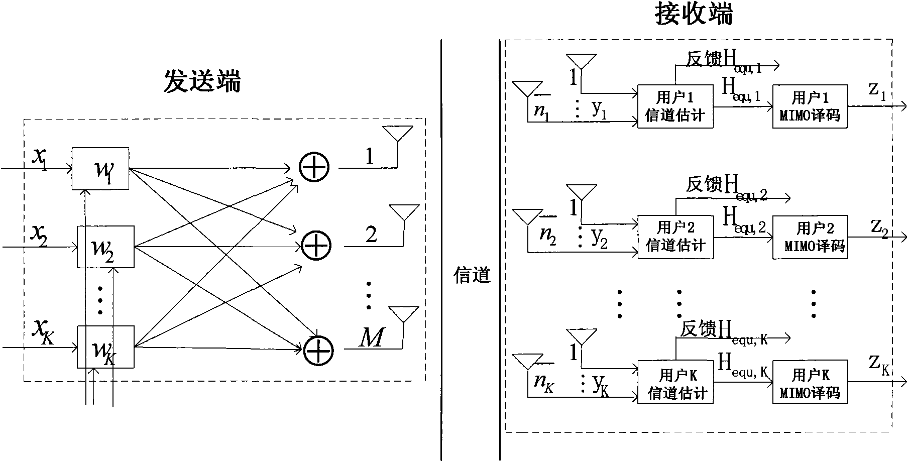
[0062] Such as figure 2 Shown is a system model diagram of the first embodiment of the present invention. In this embodiment, the base station uses feedback to obtain the channel matrix. The specific steps include:

[0063] S401: The base station stores the precoded downlink pilot symbols, and stores the precoding matrix w of all users in the system at this time t-τ ; The terminal uses the downlink pilot symbol information to perform channel estimation to obtain the equivalent channel estimation result H t,equ ; The result is the precoding matrix w transmitted at time t-τ t-τ and the channel matrix H at time t t Product H t,equ =H t w t-τ , and then the mobile station feeds back the equivalent channel estimation result H to the base station t,equ ; The base station receives the equivalent channel estimation result H at time t fed back by the terminal t,equ , extract the stored precoding matrix w at time t-τ t-τ ; put H t,equ with the precoding matrix w t-τ conjugate...

Embodiment 2

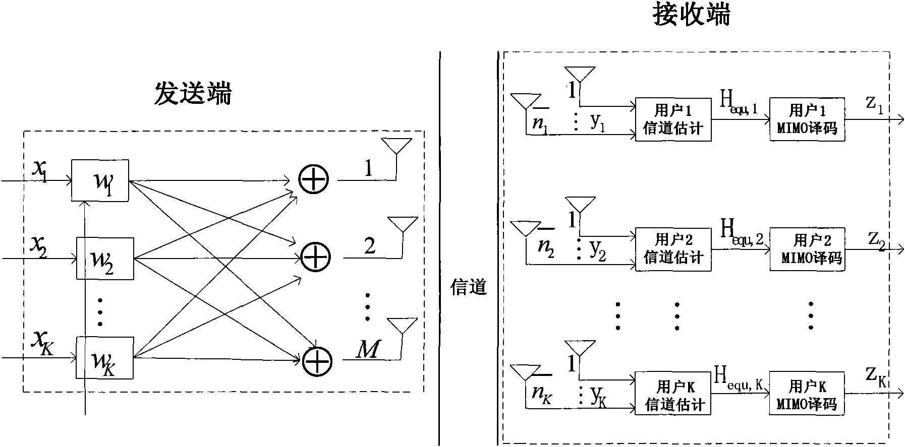
[0085] Such as image 3 Shown is a system model diagram of the second embodiment of the present invention. In this embodiment, the base station uses uplink pilot channel estimation to obtain the channel matrix. The specific steps include:

[0086] 8501: The base station uses the reciprocity of the TDD channel to directly obtain the channel matrix H of each user in the system i :

[0087] The base station uses the uplink pilot symbol information uploaded by the terminal to perform channel estimation to obtain the equivalent channel estimation result H at time t-τ t-τ,equ ; Take the result as the equivalent channel matrix H of the downlink at time t t,equ =H t-τ,equ ;

[0088] S502: The base station combines the channel matrix of each user into a channel matrix of the system The minimum mean square error matrix of the system It is based on the minimum mean square error criterion formula Obtained, where σ is the noise figure of the system, I is and HH H Identity matrix...


PUM


Abstract

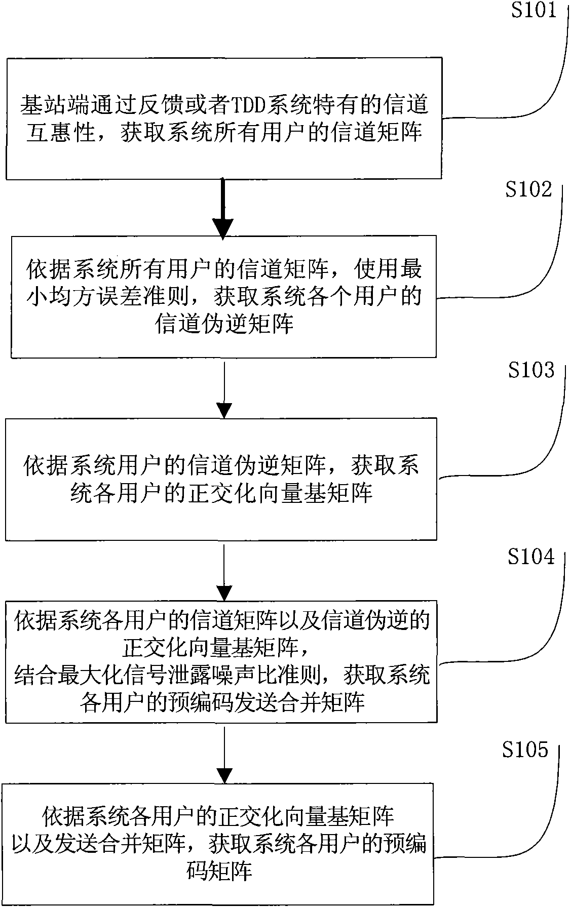
The invention provides a pre-coding method for a multi-user MIMO (multi-input multi-output) system. The method comprises the following steps of: acquiring a channel matrix of each user of the system by feedback or TDD (time division duplex) system channel reciprocity; acquiring a channel pseudo-inverse matrix of each user of the system according to the least square error criterion; acquiring an orthogonal vector base matrix according to a channel pseudo-inverse sentence of each user of the system; acquiring a pre-coding merging matrix of each user of the system according to the channel matrixof each user of the system and the channel pseudo-inverse orthogonal vector base matrix by combining a max signal to leakage and noise ratio criterion; and acquiring a pre-coding matrix of each user of the system according to the orthogonal vector base matrix of each user of the system and the optimal merging matrix. The scheme can effectively reduce the calculation complexity of the scheme at the same time of keeping the performance of the original MSLNR (max signal to leakage and noise ratio) criterion scheme, the performance of the scheme is superior to that of the traditional diagonal scheme, and the scheme has lower calculation complexity and reduces the operating complexity of a base station.

Description

technical field [0001] The invention relates to the field of communication technology, in particular to a low-complexity precoding method for a multi-user MIMO system. Background technique [0002] The multiple-input multiple-output (Multiple-Input Multiple-Output, MIMO) technology is a major breakthrough in the field of wireless mobile communication technology. MIMO technology refers to the use of multiple antennas for data transmission and reception. Studies have shown that using MIMO technology can increase the capacity of wireless communication systems. With the in-depth study of multi-antenna technology, MIMO technology has been extended from point-to-point single-user MIMO technology to point-to-multipoint multi-user MIMO system (Multiple User MIMO, MU-MIMO). In MU-MIMO technology, the multi-antenna diversity gain can effectively reduce the system bit error rate, and the multi-antenna multiplexing gain can expand the capacity area of ​​the multi-user system. MU-MIMO...

Claims


Application Information

Patent Timeline
IPC IPC(8): H04L1/06H04L1/00
Inventor 李立华张平高向川宋磊王化磊王朝炜
Owner BEIJING UNIV OF POSTS & TELECOMM
Learn More