Tubing drain

A technology of oil drainer and oil pipe, which is applied in the direction of wellbore/well parts, earthwork drilling, sealing/packing, etc., and can solve the problem that slips cannot be opened radially, connecting threads cannot be loosened, material costs and processing costs Advanced problems, to achieve the effect of low material cost and processing cost, easy processing and high operation success rate

Inactive Publication Date: 2011-03-09
白霞
View PDF8 Cites 2 Cited by
  • Summary
  • Abstract
  • Description
  • Claims
  • Application Information

AI Technical Summary

Problems solved by technology

The operator’s misoperation is due to the need to lift the oil pipe in the process of lowering the oil pipe and the hard-to-change habit formed over the years, which may cause the oil drain to be opened and drained.
Chinese patent application 00258996.6 "slip type rotary oil drainer", the slips cannot be radially opened, and cannot be stuck on the casing, so no oil is drained, since the slips can be radially opened and stuck on the casing, the oil is drained Sometimes the rear slip cannot be retracted and the pipe string is stuck, causing accidents
Another example is Chinese patent application 2007200290118 "a kind of tubing drainer", its structure is simple, but its sealing sleeve (5) and inner pipe (3) are threaded connections, because some wells have problems such as scaling and corrosion, It is easy to cause the connecting thread between the sealing sleeve (5) and the inner pipe (3) to be unable to be loosened and to prevent oil leakage
Another example is the Chinese patent application 200510043764.x "Oil Lifting Pipe Oil Drain". In order to avoid oil draining caused by the extension and shortening of the pipe string during oil pumping, the internal reaming of the release sleeve (4) is made at the position where the pipe string elongates. It will not reach the lock ball (5) when shortened, so the inner tube (1) and release sleeve (4) need to be designed to be very long, and the inner tube (1) must be processed to meet the elongation and shortening requirements caused by the operation of the oil well pump The track groove, the inner pipe (1) must use thick pipe material, therefore, the material cost and processing cost are higher

Method used


Image

  • Tubing drain
  • Tubing drain
  • Tubing drain

Examples


Embodiment Construction

[0008] The embodiments of the present invention will be described below in conjunction with the drawings.

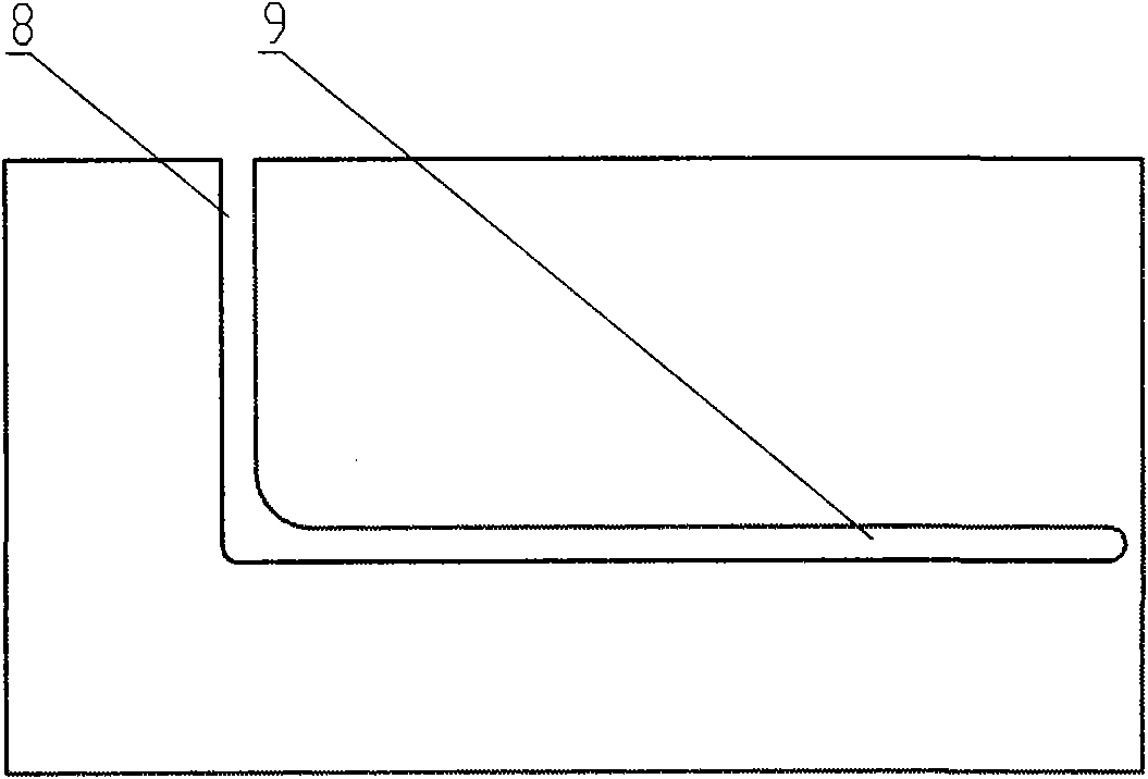
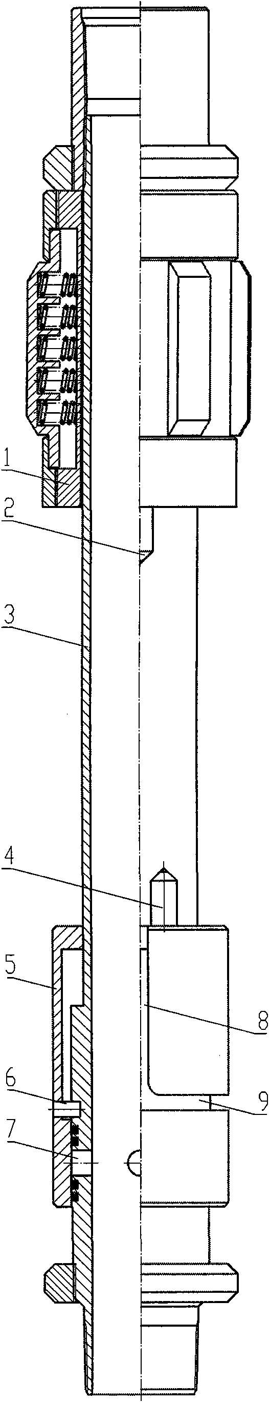
[0009] The embodiment of the present invention consists of a friction mechanism 1, an inner tube 3, a sealing sleeve 5, and a pin 6. The friction mechanism 1, the sealing sleeve 5 is sleeved outside the inner tube 3, the friction mechanism 1 is above the sealing sleeve 5, and the lower part of the inner tube 3 There is an oil drain hole 7, the lower part of the sealing sleeve 5 covers the lower oil hole 7 of the inner tube 3, the friction mechanism 1 has a convex key 2 at the lower end, and the sealing sleeve 5 has a convex key 4 at the upper end. The front end of the pin 6 is installed on the inner tube 3 to seal The sleeve 5 is provided with a vertical track groove 8 and a horizontal track groove 9, the vertical track groove 8 and the horizontal track groove 9 are communicated, the rear end of the pin 6 is in the horizontal track groove 9 on the sealing sleeve 5, and the p...


PUM


Abstract

The invention provides a tubing drain. The tubing drain consists of a friction mechanism, an inner tube and a gland cover, wherein the friction mechanism and the gland cover are sleeved outside the inner tube; the friction mechanism is arranged on the gland cover; an oil drain hole is arranged on the lower part of the inner tube; a thread is arranged on the drain hole, and is coupled with the inner thread on the upper part of the gland cover; and the lower part of the gland cover covers the drain hole on the lower part of the inner tube. When the tubing drain is connected to a defueling pump, and an oil extraction tube is required to drain oil in next operation, the oil extraction tube is assembled to ensure that two raised keys are buckled together, the inner tube is rotated, and the friction mechanism and the gland cover stand still under the friction force action between the friction mechanism and a sleeve; and under the action of turning moment, the coupled threads of the inner tube and the gland cover are released, and the gland cover moves upwards, coverage of the oil drain hole is lost to ensure that the inside and outside of the drain hole on the inner tube are communicated to drain oil. Oil drainage is performed by rotating the oil tube after the oil tube is lifted upwards in oil draining, the time for draining oil can be manually controlled at will, so the tubing drain is convenient in oil drainage, reliable in operation, high in operation success rate, simple in structure and convenient in processing and use.

Description

Technical field [0001] The invention is a downhole tool for oil extraction in an oil field, and is a tubing drain. Background technique [0002] There are many types of existing oil drains, such as Chinese patent application 96238554.9 "A Split Oil Lifting Pipe Drainer", its support type unlocking assembly will contact the oil drain assembly when the oil is lifted and drain oil. When an operator makes a mistake in operation or encounters a new situation in the process of going down the well and needs to lift the oil pipe, it will cause the oil drain to open and drain the oil, making the operation unsuccessful. Another example is the Chinese patent application 00247456.5 "Oil Lift Pipe Drainer", which also has the problems of the above patent. The operating errors of the workers are due to the need to lift the oil pipe during the process of lowering the oil pipe and the hard-to-change habit developed over the years, which may cause the opening of this type of oil drain to drain o...

Claims


Application Information

Patent Timeline
Patent Type & Authority Applications(China)
IPC IPC(8): E21B34/12
Inventor 蔺摇武张川刘新忠高军吴伟柴凯凯
Owner 白霞
Why Eureka
Try Eureka