Relaxation-type voltage-controlled oscillator
A voltage-controlled oscillator, relaxation type technology, applied in the direction of automatic power control, electrical components, etc., can solve the problems of difficult to fully match the current source, unable to produce differential output, low operating frequency, etc., to achieve high process consistency, The effect of simple structure and short oscillation period
- Summary
- Abstract
- Description
- Claims
- Application Information
AI Technical Summary
Problems solved by technology
Method used
Image
Examples
Embodiment 1
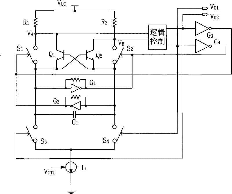
[0024] Embodiment one: see image 3 As shown, a relaxation-type voltage-controlled oscillator includes a charging capacitor, a switch tube assembly, a comparator circuit, a charging current source and a logic control circuit connected to form: one said charging current source is included; the switch tube assembly is composed of the first 1. The second group of 4 switching tubes S 1 ~S 4 Composition, the first group of switching tubes is S 1 , S 4 , the second set of switching tubes is S 2 , S 3 , where the switch tube S 1 , S 2 The control end of the logic control circuit is connected to the output end of the logic control circuit, and the switch tube S 3 , S 4 The control terminal and the oscillator output V O1 , V O2 connection, the two switching tubes in each group are connected in series, the contacts at one end of the first and second group of switching tubes are respectively connected to the charging current source, and the contacts at the other end are respect...
Embodiment 2
[0030] Embodiment two: see Figure 4 As shown, the present invention is used in the IF phase-locked loop demodulator of the TV receiver. In order to realize high-speed oscillation and have good linearity, all coupling tubes and switching tubes use bipolar transistors.
[0031] The core part is composed of 305, Q 6 , Q 7 , Q 10 , Q 11 are four switching tubes, Q 8 , Q 9 For the clamp tube, the control current source is provided by Q 12 ~Q 15 , R 10 ~R 12 composition; the control logic is composed of 309 and 311, 309 is a pair of inverters, 311 is a buffer, and has the function of level shifting; 303 is a pair of inverters; 305 is the realization image 3 G in 1 , G 2 circuit; resistance R 6 and R 7 is Q 10 and Q 11 The base bias resistors, changing their values can adjust the static operating point, so that they are completely in the "on" or "off" state, and at the same time ensure that point A has an appropriate voltage value (this voltage value will directly ...
PUM
 Abstract
Description
Claims
Application Information
 - Generate Ideas
- Intellectual Property
- Life Sciences
- Materials
- Tech Scout
- Unparalleled Data Quality
- Higher Quality Content
- 60% Fewer Hallucinations
Browse by: Latest US Patents, China's latest patents, Technical Efficacy Thesaurus, Application Domain, Technology Topic, Popular Technical Reports.
© 2025 PatSnap. All rights reserved.Legal|Privacy policy|Modern Slavery Act Transparency Statement|Sitemap|About US| Contact US: help@patsnap.com


