
PWM or PSM dual-mode modulation control circuit used for switch voltage-stabilized supply

A technology of switching regulated power supply and modulation control circuit, which is applied in the electronic field, can solve the problems of low system efficiency, achieve high efficiency, low power consumption, and improve efficiency

Inactive Publication Date: 2011-02-16
UNIV OF ELECTRONICS SCI & TECH OF CHINA
View PDF3 Cites 5 Cited by
  • Summary
  • Abstract
  • Description
  • Claims
  • Application Information

AI Technical Summary

Problems solved by technology

PSM modulation mode has the advantages of faster response and higher efficiency under light load, while in PWM modulation mode, the system efficiency is higher under heavy load, but because each clock cycle must be turned on, resulting in System efficiency is low

Method used


Image

  • PWM or PSM dual-mode modulation control circuit used for switch voltage-stabilized supply
  • PWM or PSM dual-mode modulation control circuit used for switch voltage-stabilized supply
  • PWM or PSM dual-mode modulation control circuit used for switch voltage-stabilized supply

Examples


Embodiment Construction

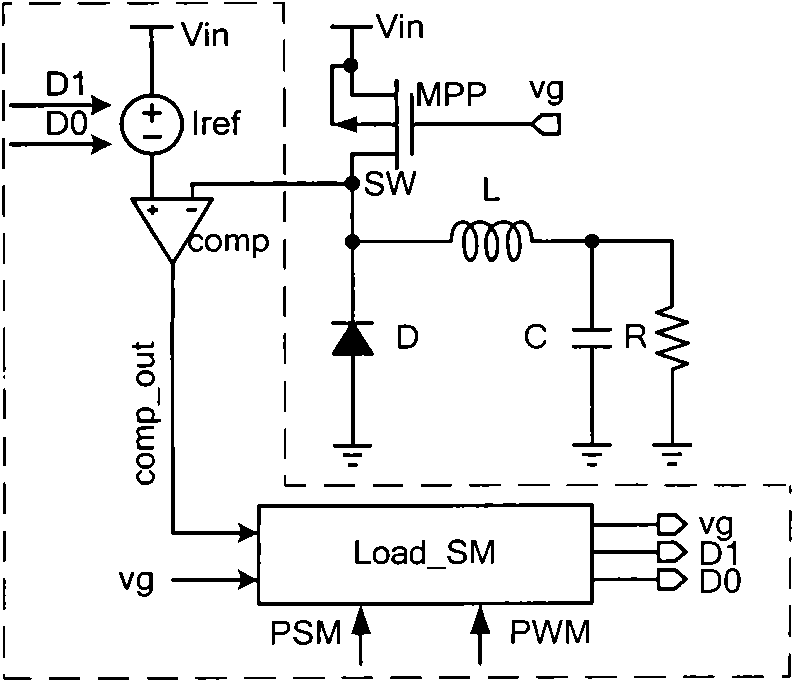
[0015] The working principle of the PWM or PSM dual-mode modulation control circuit for the switching regulated power supply provided by the present invention will be described below in conjunction with the accompanying drawings, taking a power converter with a buck structure as an example of the switching regulated power supply.

[0016] The current on the main switch tube of the buck circuit in discontinuous mode can be simulated by a triangle wave. Such as figure 2 As shown, the three PMOS transistors M01, M02 and M03 in the deep linear region in series are equivalent to a resistor, and the same gate control signal vg as the main switch is used, and the current flowing through M01, M02 and M03 is I D ;A pair of control signals D0 and D1 that are mutually inverse phases are used to control the conduction or cut-off of the NMOS transistors M2 and M3 in the controllable current reference source Iref: when D0 is high and D1 is low, M2 is on , M3 cut off, at this time the volt...


PUM


Abstract

The invention discloses a Pulse-Width Modulation (PWM) or Pulse-slope Modulation (PSM) dual-mode modulation control circuit used for a switch voltage-stabilized supply, and belongs to the technical field of electronics. The PWM or PSM dual-mode modulation control circuit comprises a controllable current reference source Iref, a comparator, a switching control circuit Load_SM, wherein the controllable current reference resource Iref generates two reference voltage signals, namely vref0 and vref1, under the control of a pair of control signals D0 and D1, which have opposite phase positions; the comparator realizes the comparison output of the voltage SM of a drain terminal of a main switch tube and the reference voltage; and the switching control circuit Load_SM automatically switches the PWM or PSM modulation mode and updates the control signals D0 and D1. The PWM or PSM dual-mode modulation control circuit selects the PWM or PSM modulation mode according to the condition of load weight so as to ensure high efficiency in a whole load range of a system. In the PWM or PSM dual-mode modulation control circuit, the load condition is judged by directly converting a current into a voltage and comparing the voltage with the reference voltage without sampling the current on a power switch tube by using a current sampling circuit. Most of the PWM or PSM dual-mode modulation control circuit is a logical circuit, has low power consumption, occupies small chip area, and can remarkably improve the efficiency of the system.

Description

technical field [0001] The invention belongs to the field of electronic technology, and relates to a control circuit of a switching and stabilizing power supply, in particular to a control circuit with a PWM or PSM dual-mode modulation mode for a switching and stabilizing power supply. Background technique [0002] The modulation methods often used in switching regulated power supplies (that is, power converters) include pulse width modulation mode PWM (PulseWidth Modulation) and pulse skip modulation mode PSM (Pulse Skip Modulation). The output of the converter is controlled by a negative feedback control loop. The voltage remains stable. The specific implementation of pulse width modulation mode PWM is: if the input voltage or load changes cause the output voltage to change, the sampling circuit samples the output voltage and compares it with the reference voltage, and then adjusts the duty of the converter switch according to the change ratio, making the output voltage s...

Claims


Application Information

Patent Timeline
Patent Type & Authority Applications(China)
IPC IPC(8): H03K7/08H02M1/08
Inventor 甄少伟罗萍余小强杨康贺雅娟张波
Owner UNIV OF ELECTRONICS SCI & TECH OF CHINA
Learn More