
Array substrate and preparation method thereof

A manufacturing method and substrate technology, applied in semiconductor/solid-state device manufacturing, optics, instruments, etc., can solve problems such as cracks in transparent conductive materials

Inactive Publication Date: 2011-02-09
CHUNGHWA PICTURE TUBES LTD
View PDF5 Cites 2 Cited by
  • Summary
  • Abstract
  • Description
  • Claims
  • Application Information

AI Technical Summary

Problems solved by technology

[0005] Therefore, the present invention provides an array substrate and its manufacturing method to solve the problem of cracks on the transparent conductive material

Method used


Image

  • Array substrate and preparation method thereof
  • Array substrate and preparation method thereof
  • Array substrate and preparation method thereof

Examples


Embodiment Construction

[0027] Certain terms are used throughout the description and claims to refer to particular components. Those of ordinary skill in the art will appreciate that manufacturers may refer to the same component by different terms. This description and subsequent patent applications do not use the difference in name as a way to distinguish components, but use the difference in function of components as a basis for distinction. The "comprising" mentioned throughout the specification and subsequent claims is an open term, so it should be interpreted as "including but not limited to".

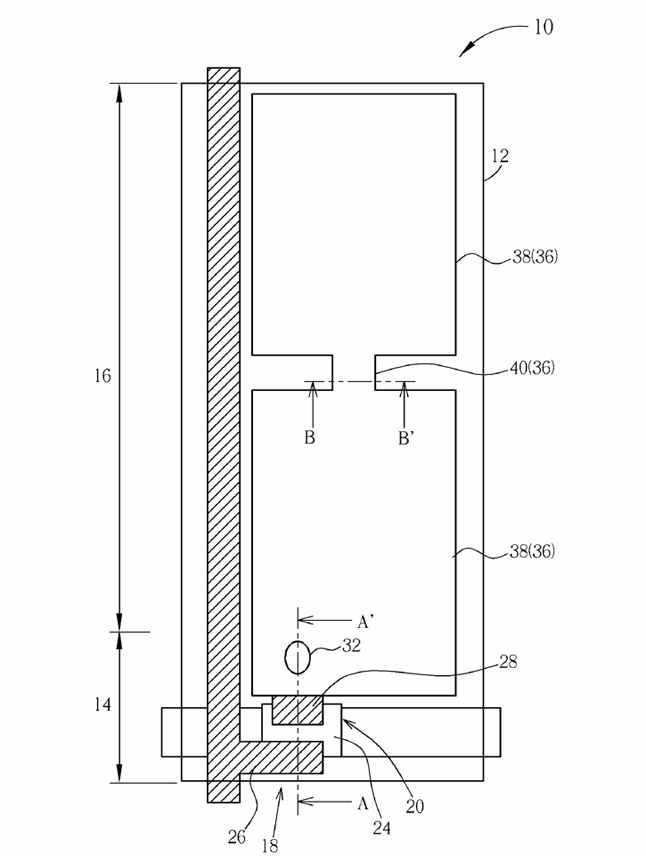
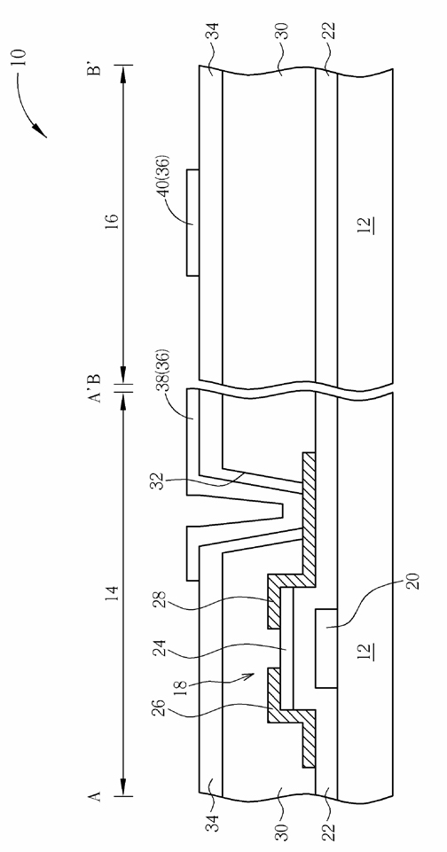
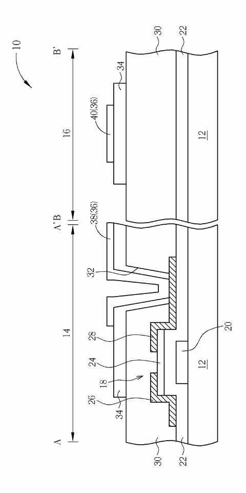
[0028] figure 1 It is a top view of an array substrate according to a preferred embodiment of the present invention. figure 2 According to the first preferred embodiment of the present invention along figure 1 The side view in the direction of the AA' section line and along the figure 1 The side view of the BB' line in the direction.

[0029] Please also see figure 1 , figure 2 , an array substr...


PUM


Abstract

The invention relates to an array substrate. The array substrate comprises a substrate, wherein a thin-film transistor which comprises a drain electrode is arranged on the substrate; an organic material layer covers the substrate and the thin-film transistor; an opening passes through the organic material layer; the drain electrode is exposed out of the opening; an inorganic material layer at least covers the side wall of the opening and part of the organic material layer; the drain electrode is exposed out of the opening; and a patterned transparent pixel electrode layer is positioned on the inorganic material layer and in the opening and contacts the drain electrode.

Description

technical field [0001] The invention relates to a manufacturing method and structure of an array substrate, in particular to a manufacturing method and structure of an array substrate capable of avoiding cracks in transparent electrodes. Background technique [0002] Among various image display technologies today, liquid crystal panels have been widely used in various electronic devices due to their advantages of light weight, small size, low power consumption, and no radiation. [0003] Generally speaking, a plurality of scanning lines and a plurality of data lines are arranged on an array substrate of the liquid crystal panel. The scanning lines and the data lines are arranged alternately, and the substrate is divided into a plurality of pixel units. Each pixel unit has a pixel electrode and a thin film transistor. The thin film transistor is coupled to the scan line and the data line, and serves as a switch component of the pixel electrode. In the substrate of the tran...

Claims


Application Information

Patent Timeline
IPC IPC(8): H01L21/77G02F1/1368G02F1/1362H01L27/12H01L29/41
Inventor 张锡明
Owner CHUNGHWA PICTURE TUBES LTD
Learn More