
Wound motor rotor conductive ring protection mode and fixing device

A technology for motor rotors and fixing devices, which is applied in the direction of electromechanical devices, manufacturing motor generators, asynchronous induction motors, etc., can solve the problems of damaging the binding of the rotor end, occupying space, wasting manpower and material resources, etc., and achieves the convenience of replacing the conductive ring. Easy installation and replacement, saving manpower and material resources

Active Publication Date: 2012-07-25
CSR ZHUZHOU ELECTRIC CO LTD
View PDF0 Cites 0 Cited by
  • Summary
  • Abstract
  • Description
  • Claims
  • Application Information

AI Technical Summary

Problems solved by technology

[0003]At present, the conductive rings of large and medium-sized wound motors are generally fixed by built-in binding or surface binding. There are different degrees of deficiencies, and it takes up a lot of space, and it is inconvenient to replace. Especially when the built-in binding type is used, replacing a conductive ring often destroys the binding at the end of the entire rotor, wasting a lot of manpower and material resources.
With the changes in the application environment of wound motors, the power and performance of wound motors are constantly improving, and the safe fixing of the rotor conductive ring is becoming more and more important. The traditional fixing methods are not enough to meet the requirements of higher performance. more obvious

Method used


Image

  • Wound motor rotor conductive ring protection mode and fixing device
  • Wound motor rotor conductive ring protection mode and fixing device
  • Wound motor rotor conductive ring protection mode and fixing device

Examples


Embodiment Construction

[0018] The present invention will be further described below in conjunction with the accompanying drawings.

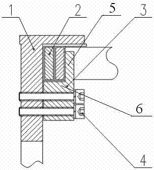
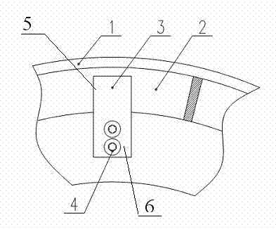
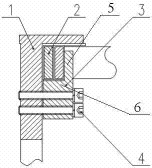
[0019] figure 1 and figure 2 A structural embodiment of the present invention is given. The present invention is a protection method for the conductive ring of the rotor of a wire-wound motor. First, the conductive rings wrapped with insulation are pushed into the end bracket one by one. Stacking together can also be radial stacking, and then use a compression block to compress the conductive ring on the bracket. Each compression block has two through holes for assembling bolts. Through two standard bolts and The end bracket is fastened, and the size and grade of the bolts are determined according to the force, so as to ensure that the compression block can securely fix each conductive ring, so that they form a gap-free whole, free from the damage of centrifugal force, thereby protecting Conductive rings of wound motor rotors.

[0020] The utility model relates to ...


PUM


Abstract

The invention discloses a wound motor rotor conductive ring protection mode and a fixing device. Rotor conductive rings are fixed in the cavity at the end of a rotor winding by adopting a compaction structure. The compaction structure mainly comprises an end bracket, compaction blocks and conductive rings, wherein the pre-packed insulated conductive rings are pushed into the end bracket one by one, and then the conductive rings are compacted on the bracket by using the compaction blocks to form a gapless whole so as to avoid the damage of the centrifugal force; the end bracket can be welded by adopting different nonmagnetic steel plates and also can be cast by cast steel; and the compaction blocks are processed by nonmagnetic steel plates, and each compaction block is provided with two through holes for assembling bolts. In addition, screw holes can be processed at different positions of the compaction surface of the end bracket as required. Each compaction block is fastened with the end bracket through two standard bolts, and the size and the grade of the bolts are determined according to the stress condition so as to ensure that the conductive rings can be safely fixed by the compaction blocks.

Description

technical field [0001] The invention relates to a component protection method and device for a wound-type motor rotor, in particular to a protection method and a fixing device for a motor rotor conductive ring. The wire-wound motor rotor conductive ring protection method and the fixing device can effectively protect The conductive rings of the rotor are more reliable in fixing and more convenient in replacement, economical and practical, especially suitable for various large and medium-sized winding motor rotors. Background technique [0002] For the wound motor rotor, it is divided into "△" and "Y" connection. The neutral wire of the rotor of the two types of connections and the lead wires of each parallel branch need to be connected at the end of the rotor, and this connection part is usually called a conductive ring. Generally, the conductive ring is made of copper, and its mechanical and physical properties are relatively weak. When the motor rotates at high speed, the ...

Claims


Application Information

Patent Timeline
Patent Type & Authority Patents(China)
IPC IPC(8): H02K17/22H02K15/00
Inventor 龚天明
Owner CSR ZHUZHOU ELECTRIC CO LTD
Learn More