
Crushing shaft of rubber rubbing and cutting machine

A crushing shaft and cutting machine technology, which is applied in the direction of mechanical material recovery, recycling technology, grain processing, etc., can solve the problems of step 102 wear, high power consumption of crushing, easy damage of flat keys, etc., so as to avoid blockage and improve service life effect on reliability

Inactive Publication Date: 2011-01-26
江阴市鑫达药化机械制造有限公司
View PDF8 Cites 3 Cited by
  • Summary
  • Abstract
  • Description
  • Claims
  • Application Information

AI Technical Summary

Problems solved by technology

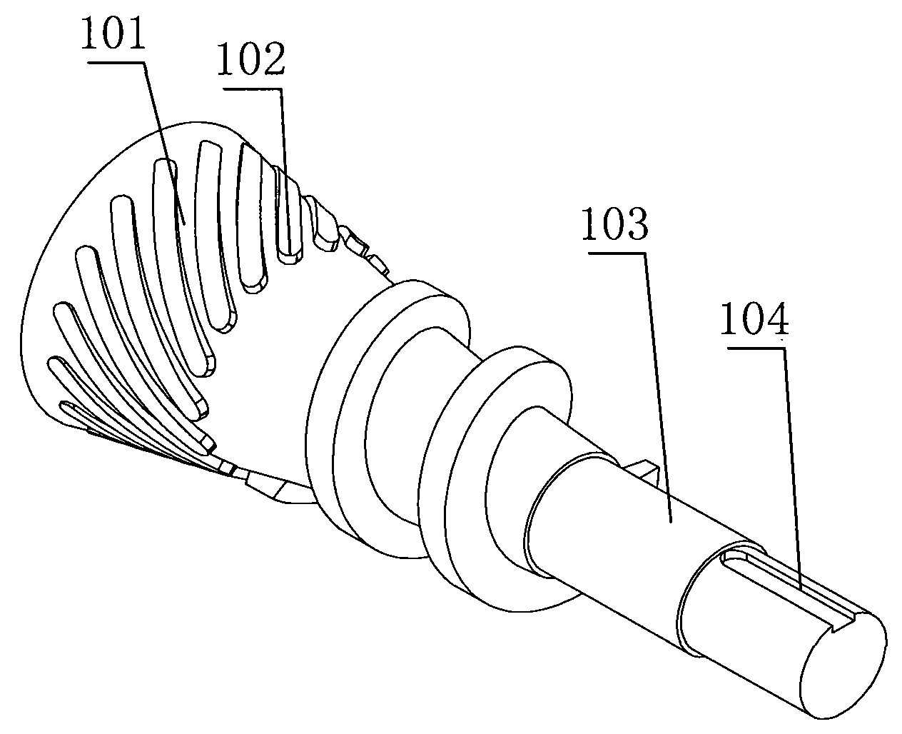
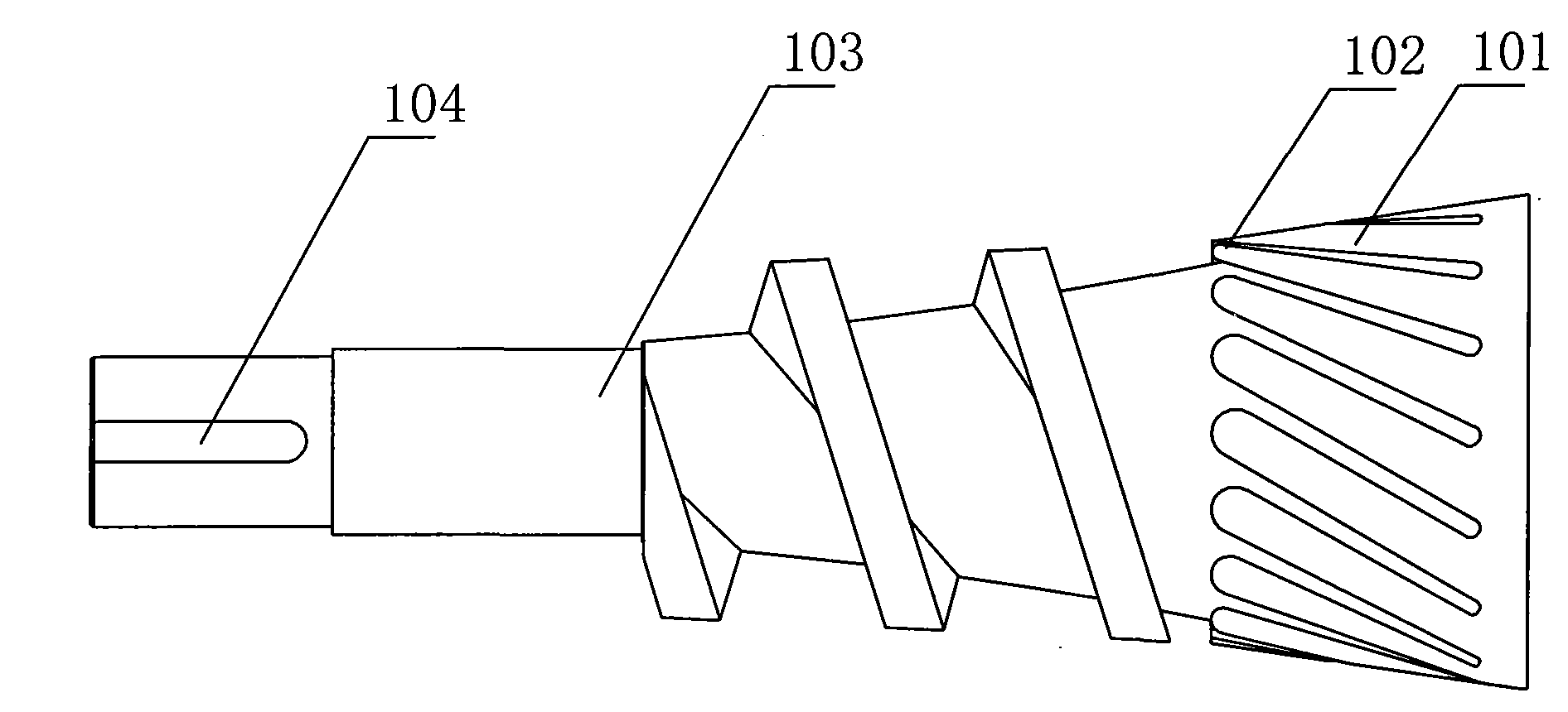
But the pulverizing shaft of current rubbing cutter, such as figure 1 As shown, the helical blade 101 and the cutter shaft 103 have an integrated structure, which has the following disadvantages: 1. Rubber is a tough material, and the power consumption of crushing is large, so the crushing shaft blade and the inner sleeve of the crushing box are very serious. However, the current integrated After the blade is worn out, only the entire shaft can be replaced, which is time-consuming, laborious and costly
2. The structure of the crushing shaft of the current rubbing machine is unreasonable. There is a step 102 on the cross section. The rubber blocks to be crushed are crowded and blocked at this step 102, causing serious wear on the step 102.
3. The groove of the current spiral blade 101 is relatively wide, with a width of 15 mm, and the rubber particles cut out by rubbing are relatively large
4. The end of the cutter shaft adopts a flat key and keyway 104 connection structure, and the flat key is easily damaged by a large shearing force

Method used


Image

  • Crushing shaft of rubber rubbing and cutting machine
  • Crushing shaft of rubber rubbing and cutting machine
  • Crushing shaft of rubber rubbing and cutting machine

Examples


Embodiment Construction

[0015] The specific implementation manner of the present invention will be described below in conjunction with the accompanying drawings.

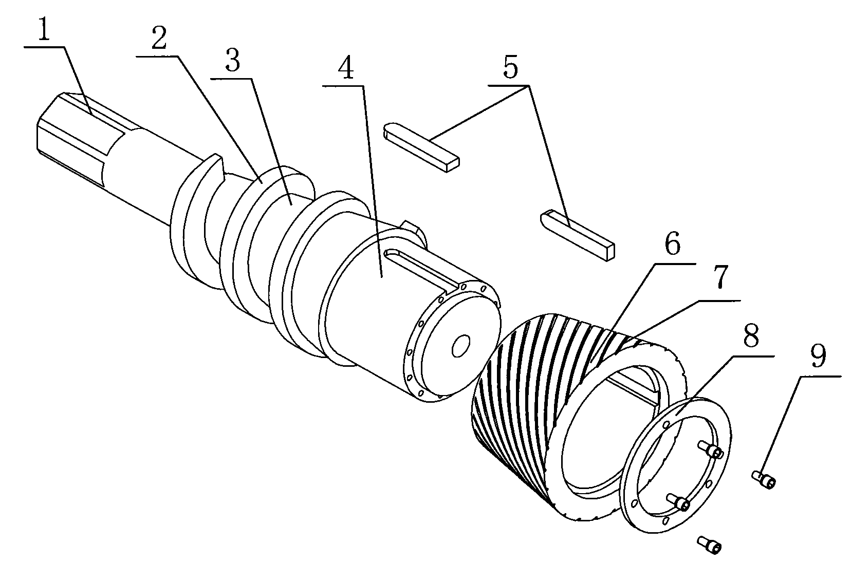
[0016] Such as image 3 , Figure 4 As shown, the crushing shaft outer sleeve 6 and the main shaft 3 of the present invention are separable structures, the rear section of the main shaft 3 is a clamping part 1, the middle part is a screw conveying part 2, and the front part is a knife holder fixing part 4; the clamping part 1 is The hexagonal shaft structure, compared with the flat key structure used in the existing rubbing machine main shaft clamping part, can effectively increase the rotational torque transmitted by the main shaft and prevent the flat key from being sheared and damaged; the outer surface of the screw conveying part 2 in the middle , including the side, top and groove bottom of the helical blade are welded with cemented carbide layer, which can effectively avoid the damage of the helical surface; The split crushing shaf...


PUM

PropertyMeasurementUnit
Widthaaaaaaaaaa

Abstract

The invention relates to a crushing shaft of a rubber rubbing and cutting machine, which comprises separable crushing shaft sleeve and spindle. The crushing shaft sleeve is fixed to the spindle through an end part fixing structure and a keyslot structure. The easily worn crushing shaft sleeve can be quickly and efficiently replaced; the reasonable section shape prevents the blockage of materials on a rubbing and cutting part; a thinner cutter groove can process fine rubber particles; a hexagonal axis clamping part can transfer larger torque; and the crushing shaft has the advantages of reasonable structure, convenient maintenance, good reliability and long service life.

Description

technical field [0001] The invention relates to the field of rubber processing equipment, in particular to recycling and processing equipment for waste rubber. Background technique [0002] Recycling and processing of waste rubber products such as car tires and shoe soles requires the rubber products to be initially cut into strips of rubber with a width of about 5 cm, and then the rubber blocks are crushed into rubber particles of about 5 mm with a rubber rubbing cutter. The rubber block is squeezed and rubbed between the conical crushing shaft of the rubber rubbing cutter and the inner sleeve of the crushing box, and crushed into fine particles under the joint action of extrusion force and shearing force. But the pulverizing shaft of current rubbing cutter, such as figure 1 As shown, the helical blade 101 and the cutter shaft 103 have an integrated structure, which has the following disadvantages: 1. Rubber is a tough material, and the power consumption of crushing is lar...

Claims


Application Information

Patent Timeline
IPC IPC(8): B29B17/04B02C18/18
CPCY02W30/52Y02W30/62
Inventor 顾军顾洪
Owner 江阴市鑫达药化机械制造有限公司
Learn More