
Rotor of alternating-current asynchronous motor

A technology for AC asynchronous motors and rotors, applied in asynchronous induction motors, manufacturing stator/rotor bodies, electrical components, etc., can solve problems that affect the service life of motors, time-consuming and labor-intensive, waste of punching, etc., and achieve the elimination of hidden dangers and effective effects Obvious effect of improving production efficiency

Active Publication Date: 2011-01-19
SEC ELECTRIC MACHINERY
View PDF4 Cites 2 Cited by
  • Summary
  • Abstract
  • Description
  • Claims
  • Application Information

AI Technical Summary

Problems solved by technology

Turning the outer circle of the rotor is good for ensuring concentricity, but turning is not only time-consuming and labor-intensive, the off-cut punches are directly wasted, and if the iron filings are not cleaned up during processing, they will enter the air passage between the punches, and when the rotor rotates at a high speed Sometimes iron filings fly out, splashing on the stator coil will cause different degrees of damage to the insulation, and even cause blasting in severe cases, directly affecting the service life of the motor

Method used


Image

  • Rotor of alternating-current asynchronous motor
  • Rotor of alternating-current asynchronous motor
  • Rotor of alternating-current asynchronous motor

Examples


Embodiment Construction

[0010] The present invention will be further described below in conjunction with specific drawings.

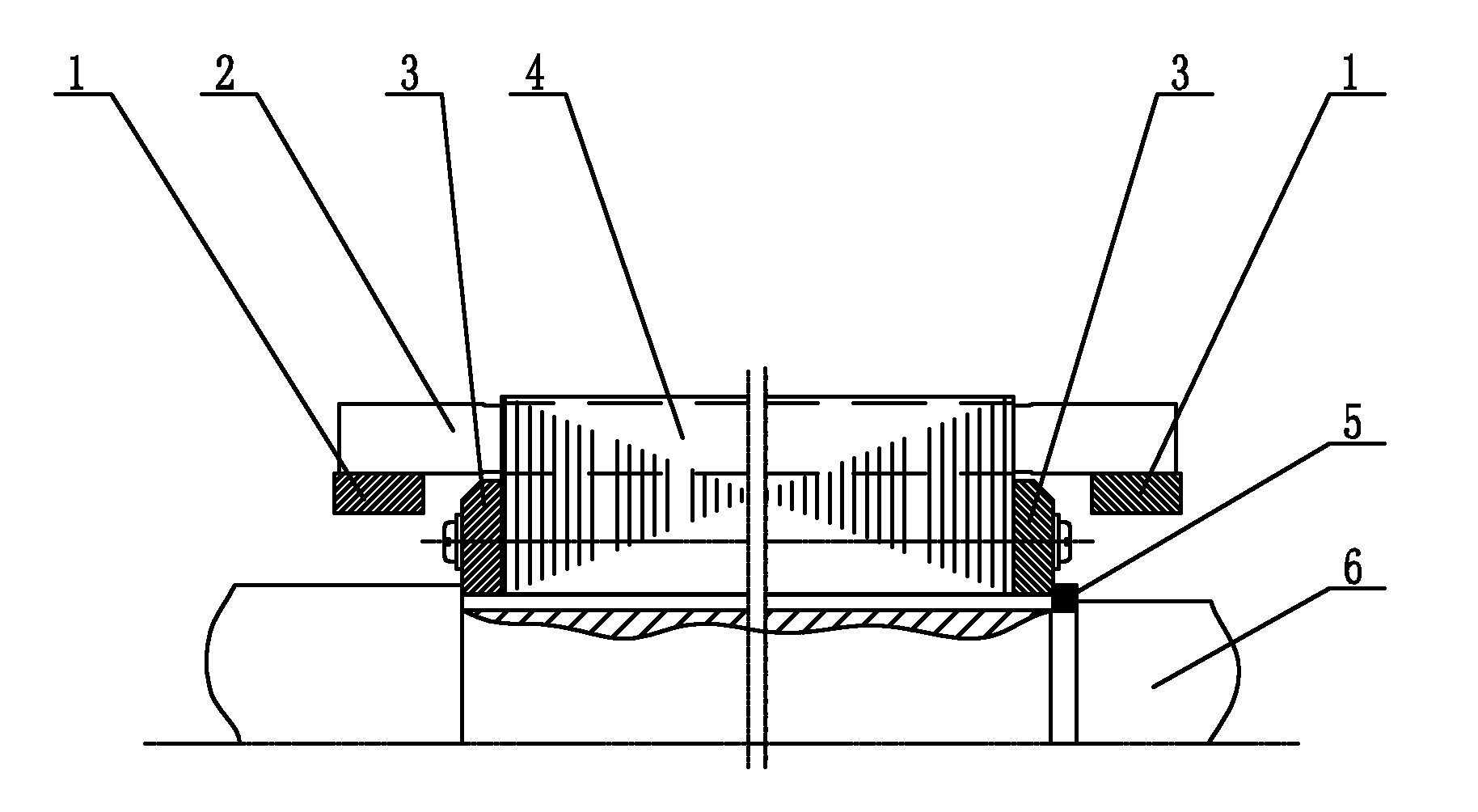
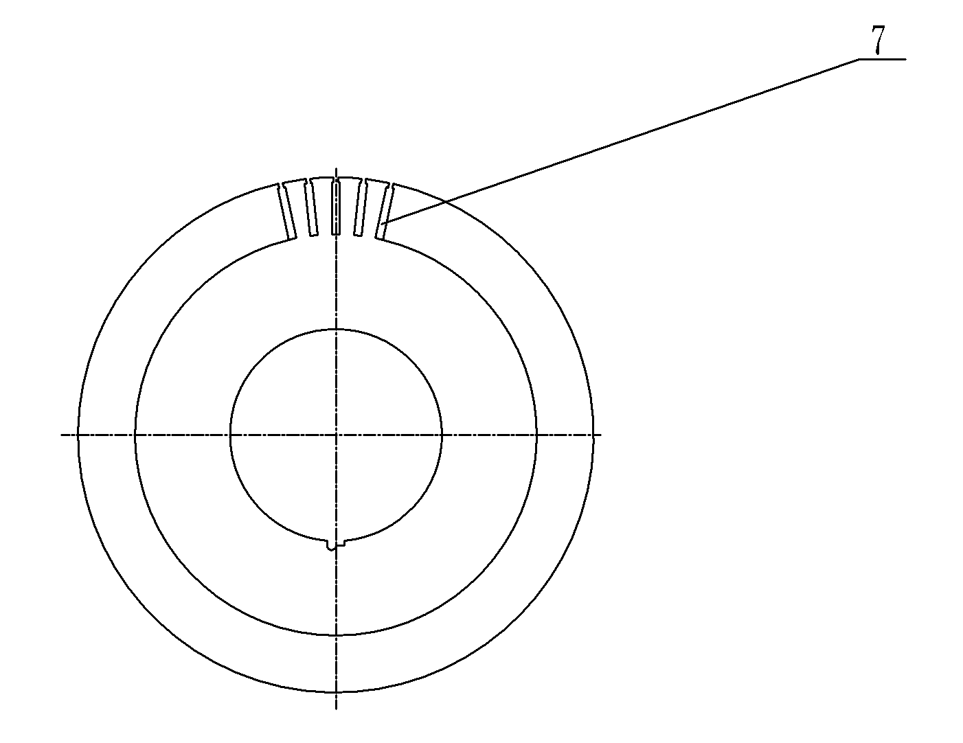
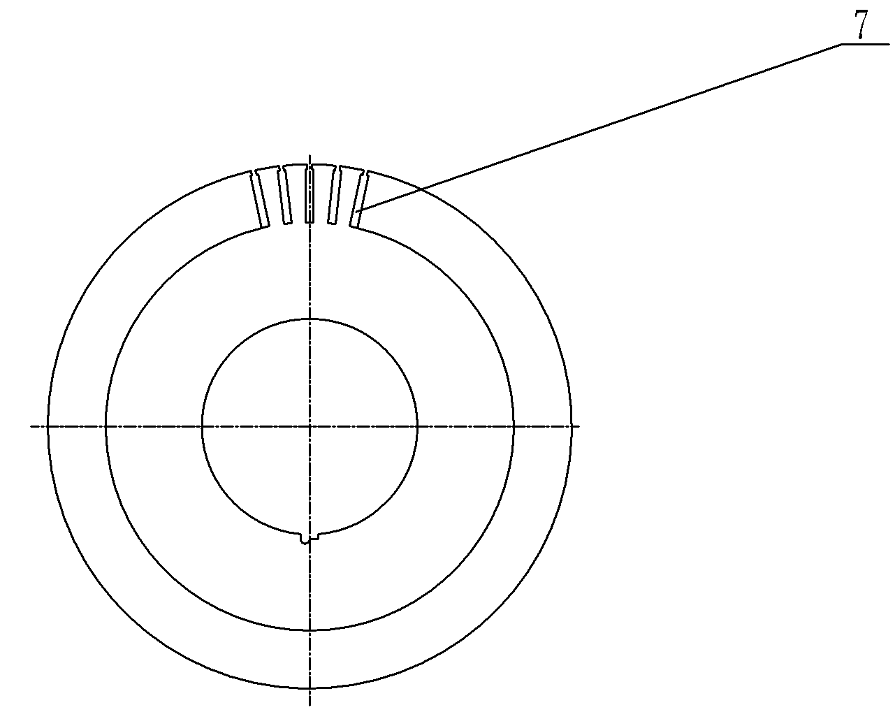
[0011] Such as Figure 1~Figure 2 As shown: the rotor of an AC asynchronous motor includes an end ring 1, a conductive rod 2, a rotor pressure ring 3, a rotor core 4, an arc key 5, a shaft 6, and a punching groove 7.

[0012] The present invention includes a rotor core 4 sleeved on the shaft 6, and rotor pressure rings 3 are arranged at both ends of the rotor core 4; the rotor core 4 is formed by stacking several rotor punches, and a Several punching grooves 7, one end of the punching groove 7 points to the center of the rotor punching sheet, and the other end of the punching groove 7 is open; the outer diameter of the rotor punching sheet is equal to the outer diameter of the rotor core 4;

[0013] A conductive rod 2 is arranged in the punching slot 7, and an end ring 1 is connected to the inner side of the end of the conductive rod 2;

[0014] The end of the shaft 6 is pro...


PUM


Abstract

The invention relates to a rotor of an alternating-current asynchronous motor, which comprises a rotor iron core sleeved on a shaft. A rotor clamping ring is respectively arranged at two ends of the rotor iron core; the rotor iron core consists of a plurality of rotor punching sheets by superposition; the edges of the punching sheets are provided with a plurality of sheet-punching grooves; one end of each sheet-punching groove points at the centers of the rotor punching sheets; and the other end of each sheet-punching groove is open. The alternating-current asynchronous motor is characterized in that the outside diameter of the rotor punching sheets is equal to that of the rotor iron core. A conducting rod is arranged in the sheet-punching grooves; an end ring is connected to the inner side at the end part of the conducting rod; the end part of the shaft is provided with a key groove; and an arc key for fixing the rotor iron core is arranged in the key groove. The invention has the advantages of simple structure, safety and obvious effect. Under the conditions of ensuring the safety and the reliability of the motor and keeping the electromagnetic design unchangeable, the processing time and the sheet-punching material are saved by changing the design of the punching sheets, thereby improving production efficiency and eliminating incipient faults in use.

Description

technical field [0001] The invention relates to a rotor, especially a rotor for a three-phase asynchronous motor. Background technique [0002] For a long time, many motor factories in the motor industry have required the technical department to process the outer circle of the rotor to ensure the concentricity of the outer circle of the rotor during the production of the motor. The general machining allowance is about 0.3mm on one side. In the early days, the stamping pieces punched by the separation die were even processed by a few millimeters (the air gap was processed). Turning the outer circle of the rotor is good for ensuring concentricity, but turning is not only time-consuming and labor-intensive, the off-cut punches are directly wasted, and if the iron filings are not cleaned up during processing, they will enter the air passage between the punches, and when the rotor rotates at a high speed Sometimes iron filings fly out, splashing on the stator coil will cause dif...

Claims


Application Information

Patent Timeline
Patent Type & Authority Applications(China)
IPC IPC(8): H02K17/12H02K1/22H02K15/02
Inventor 王坤
Owner SEC ELECTRIC MACHINERY
Learn More