Observation device
A technology of observation device and wave front, applied in the field of observation device
- Summary
- Abstract
- Description
- Claims
- Application Information
AI Technical Summary
Problems solved by technology
Method used
Image
Examples
no. 1 approach
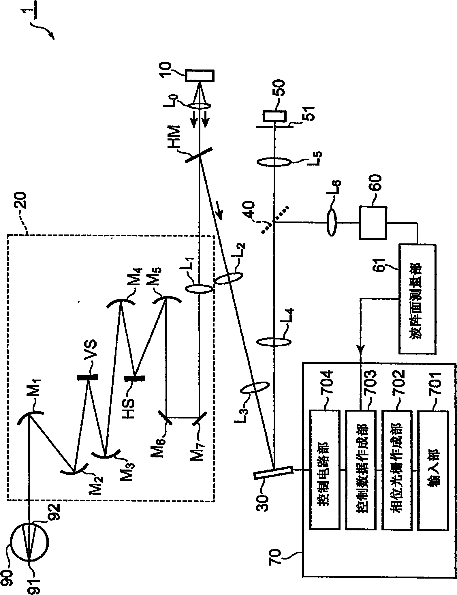
[0038] First, the observation device according to the first embodiment will be described. figure 1 It is a configuration diagram of the observation device 1 according to the first embodiment. The observation device 1 shown in the figure is a scanning fundus imaging device suitable for observing the fundus 91 of the eye 90 as an object, and has a light source unit 10, a two-axis scanning system 20, a wavefront modulation unit 30, and a light branching unit 40. , the photodetection unit 50, the wavefront detection unit 60, the control unit 70, and the like.
[0039] The light source unit 10 is a component that outputs light to be irradiated to the fundus 91, and preferably includes a light emitting element that can be regarded as a point light source such as a laser diode (LD) and a super luminescent diode (SLD). The light output from the optical part 10 passes through the lens L 0 The light becomes parallel light, passes through the half-mirror HM, and is input to the two-axi...
no. 2 approach
[0090] Next, an observation device according to a second embodiment will be described. Figure 10 It is a configuration diagram of the observation device 2 according to the second embodiment. The observation device 2 shown in this figure is a device suitable for a biological microscope for observing a biological sample 94 as an object placed on a stage 93, and the observation device includes: a light source unit 10A, a light source unit 10B, the wavefront modulation unit 30 , the light branching unit 40 , the light detection unit 50 , the wavefront detection unit 60 , the control unit 70 and the like.
[0091] In order to protect the target biological sample 94 placed on the stage 93 , the biological sample 94 is covered with a cover glass 95 . The cover glass 95 will also cause deformation of the wavefront of light, so it is necessary to use wavefront aberration compensation technology to compensate the wavefront of light. In addition, in the present embodiment, the observa...
no. 3 approach
[0098] Next, an observation device according to a third embodiment will be described. Figure 11 It is a configuration diagram of the observation device 3 according to the third embodiment. The observation device 3 shown in this figure includes: a light source unit, a first wavefront modulating element 31 and a second wavefront modulating element 32 as a wavefront modulating unit, a light branching unit 40, a photodetecting unit 50, a wavefront The surface detection unit 60, the control unit 71, the control unit 72, and the like. In addition, in the drawing, the illustration of the structure from the light source unit to the first wavefront modulation element 31 via the object is omitted.
[0099] The first wavefront modulation element 31 exhibits a compensating phase pattern for compensating wavefront distortion of light. The second wavefront modulation element 32 exhibits a branching phase pattern for branching the first and second lights. A lens L is provided on the opti...
PUM
 Abstract
Description
Claims
Application Information
 - R&D
- Intellectual Property
- Life Sciences
- Materials
- Tech Scout
- Unparalleled Data Quality
- Higher Quality Content
- 60% Fewer Hallucinations
Browse by: Latest US Patents, China's latest patents, Technical Efficacy Thesaurus, Application Domain, Technology Topic, Popular Technical Reports.
© 2025 PatSnap. All rights reserved.Legal|Privacy policy|Modern Slavery Act Transparency Statement|Sitemap|About US| Contact US: help@patsnap.com


