Nitride semiconductor chip, method of fabrication thereof, and semiconductor device
A nitride semiconductor and manufacturing method technology, which is applied in semiconductor/solid-state device manufacturing, semiconductor lasers, laser parts and other directions, and can solve problems such as low luminous efficacy, surface morphology deterioration of nitride semiconductor layers, and low gain.
- Summary
- Abstract
- Description
- Claims
- Application Information
AI Technical Summary
Problems solved by technology
Method used
Image
Examples
Embodiment 1
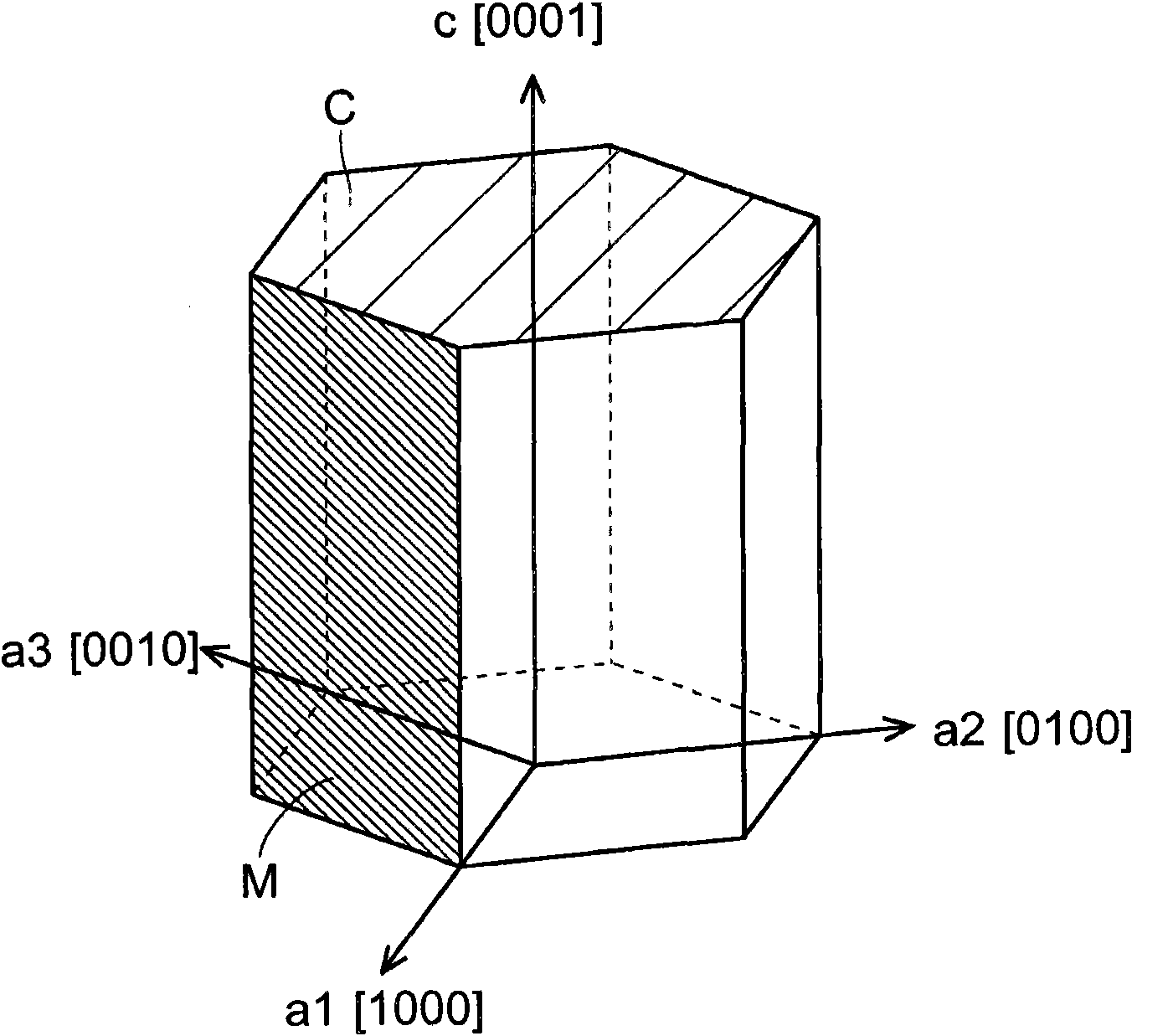
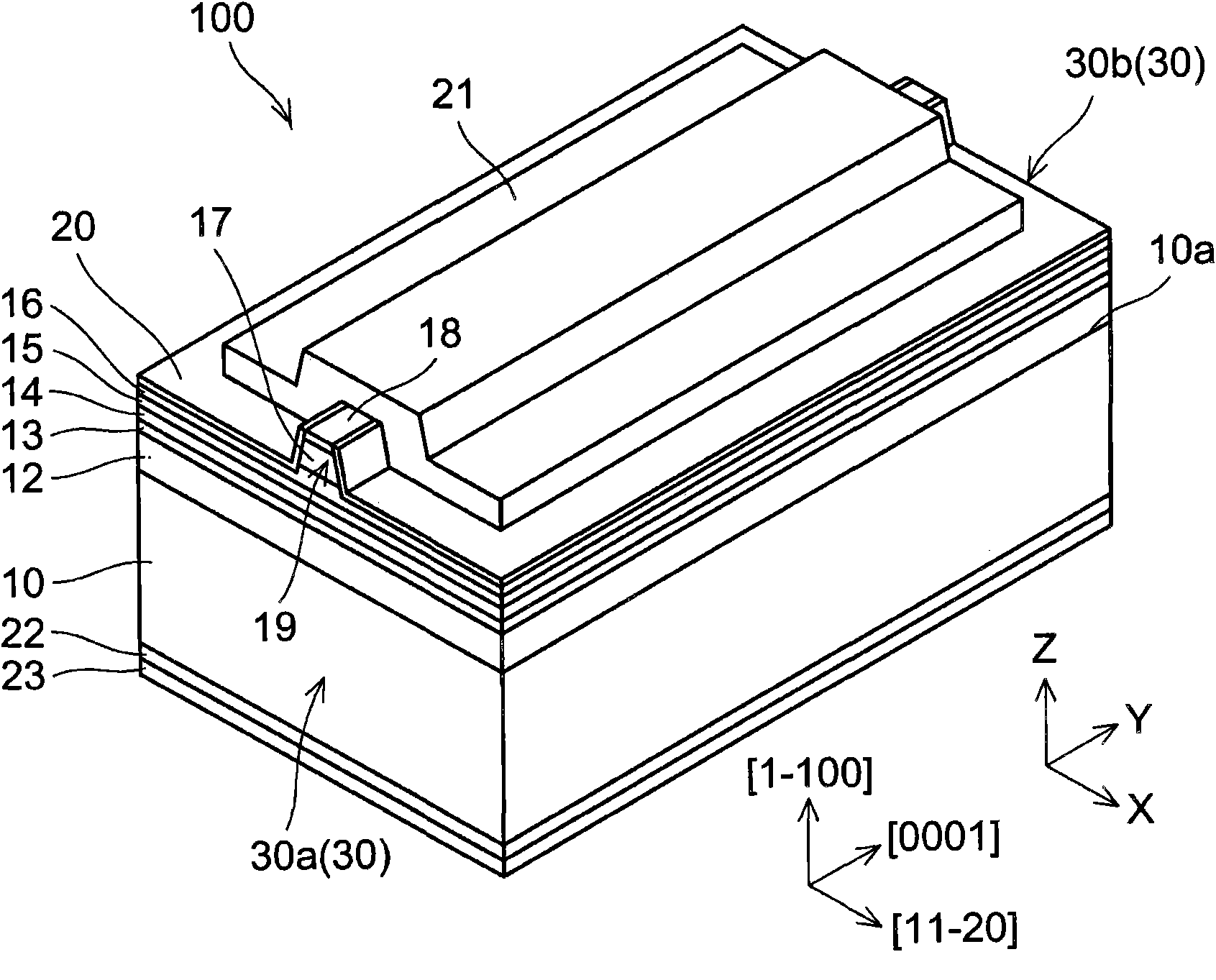
[0159] figure 1 is a schematic diagram showing a crystal structure of a nitride semiconductor. figure 2 is a cross-sectional view showing the structure of a nitride semiconductor laser chip according to a first embodiment (Embodiment 1) of the present invention. image 3 is an overall perspective view of a nitride semiconductor laser chip according to Embodiment 1 of the present invention. Figure 4 to Figure 6 is a view showing the structure of a nitride semiconductor laser chip according to Embodiment 1 of the present invention. First, refer to Figures 1 to 6 , the structure of the nitride semiconductor laser chip 100 according to Embodiment 1 of the present invention will be described.
[0160] The nitride semiconductor laser chip 100 according to Embodiment 1 consists of a figure 1 The nitride semiconductor is formed with a hexagonal crystal structure shown. In this crystal structure, when the hexagonal system is regarded as a hexagonal column about the c-axis [00...
Embodiment 2
[0226] Figure 23 is a cross-sectional view showing the structure of a nitride semiconductor laser chip according to a second embodiment (Embodiment 2) of the present invention. Figure 24 is an overall perspective view of a nitride semiconductor laser chip according to Embodiment 2 of the present invention. Figure 25 with Figure 26 is a view showing the structure of a nitride semiconductor laser chip according to Embodiment 2 of the present invention. Next, refer to Figures 23 to 26 , the structure of a nitride semiconductor laser chip 1100 according to Embodiment 2 of the present invention will be described.
[0227] Such as Figure 23 with 24 As shown, a nitride semiconductor laser chip 1100 according to Embodiment 2 is formed by using a GaN substrate 10 similar to the previously described Embodiment 1, and has a plurality of nitride semiconductor laser chips stacked on the main growth plane 10a of the GaN substrate 10 Floor. That is, in Embodiment 2, like Embodim...
example 4
[0288] As the nitride semiconductor laser chip according to Practical Example 4, by using a GaN substrate having an off-angle of 6 degrees in the a-axis direction and an off-angle of -1.1 degrees in the c-axis direction with respect to the m-plane {1-100} , where the barrier layer consists of Al s In t Ga u A nitride semiconductor laser chip formed of N(s+t+u=1) was fabricated. In Practical Example 4, the first barrier layer is made of Al s In t Ga u N (s=0.01, t=0, u=0.99), the second and third barrier layers are made of Al s In t Ga u N (s=0.02, t=0.01, u=0.97) formed. That is, in Practical Example 4, the first barrier layer is formed of AlGaN, and each of the second and third barrier layers is formed of AlInGaN. The structure of Practical Example 4 is similar to that of the above-described embodiment (Practical Example 2) except for other aspects of the barrier layer. Practical Example 4 provides effects similar to those of Practical Example 2 above. Incidentally...
PUM
 Abstract
Description
Claims
Application Information
 - R&D
- Intellectual Property
- Life Sciences
- Materials
- Tech Scout
- Unparalleled Data Quality
- Higher Quality Content
- 60% Fewer Hallucinations
Browse by: Latest US Patents, China's latest patents, Technical Efficacy Thesaurus, Application Domain, Technology Topic, Popular Technical Reports.
© 2025 PatSnap. All rights reserved.Legal|Privacy policy|Modern Slavery Act Transparency Statement|Sitemap|About US| Contact US: help@patsnap.com


