
LED (Light Emitting Diode) condensing lens

A concentrating lens and lens technology, applied in the field of lighting, can solve problems such as uneven spot, and achieve the effect of small beam divergence angle

Inactive Publication Date: 2011-01-12
OCEANS KING LIGHTING SCI&TECH CO LTD +1
View PDF0 Cites 15 Cited by
  • Summary
  • Abstract
  • Description
  • Claims
  • Application Information

AI Technical Summary

Problems solved by technology

[0003] The technical problem to be solved by the present invention is to provide an LED condenser lens capable of forming a circular and uniform light spot in view of the defects of non-circular light spots and uneven light spots formed by LEDs in the prior art

Method used


Image

  • LED (Light Emitting Diode) condensing lens
  • LED (Light Emitting Diode) condensing lens
  • LED (Light Emitting Diode) condensing lens

Examples


Embodiment Construction

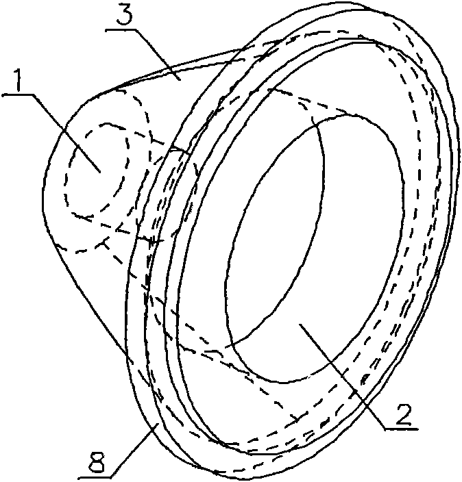
[0026] Such as figure 1 , 2 Shown is an LED condenser lens, the lens is a truncated cone lens made of optical material with a refractive index of 1.4-1.7. The optical material specifically selected is PMMA or PC material, and the refractive index of PMMA material is 1.494, and the refractive index of PC material is 1.591, and the rear end face of frustum-shaped lens has cylindrical first refraction groove 1, and lens front face has cylindrical first refraction groove 1. The second refraction groove 2, the outer wall 3 of the lens is a total reflection surface, and the groove walls of the first refraction groove 1 and the second refraction groove 2 form a refraction surface. Wherein the refraction surface of the first refraction groove 1 is its surrounding side wall 5 and bottom surface 6 respectively, the refraction surface of the second refraction groove 2 is its bottom surface 7, and the first refraction groove 1 and the second refraction groove 2 are symmetrical about the ...


PUM


Abstract

The invention discloses an LED condensing lens which is a round table type lens, wherein the rear end surface of the round table type lens is provided with a first cylindrical refraction groove, the front end surface of the round table type lens is provided with a second cylindrical refraction groove, the outside wall of the round table type lens is a fully reflecting surface, and the groove walls of the first cylindrical refraction groove and the second cylindrical refraction groove form a refraction surface. The invention provides the LED condensing lens which can form even and round spots and has the advantages of small beam divergence angles, high light condensation and high light efficiency.

Description

technical field [0001] The invention belongs to the technical field of illumination and relates to a lens, in particular to an LED condenser lens. Background technique [0002] With the improvement of LED packaging technology, there are various methods of coating phosphor on LED chips. The traditional method is to completely cover the chip with phosphor, so that the square chip inside cannot be seen from the appearance. At present, the new phosphor coating method only applies the phosphor thinly and evenly on the surface of the chip, so that the packaged LED can see the square chip inside from the outside. The above two kinds of LEDs have been widely used, but in terms of light efficiency, the light effect of the new phosphor coating method of the latter is higher than that of the former, and the application amount is mostly. However, the condensing lens matching the above two LEDs on the market is the same. The lens is provided with a plano-convex lens part near the center...

Claims


Application Information

Patent Timeline
IPC IPC(8): F21V5/04H01L33/00F21Y101/02
Inventor 周明杰刘廷明
Owner OCEANS KING LIGHTING SCI&TECH CO LTD
Learn More