
Computer numerical control constant force spring machine

A constant force spring, computer technology, applied in the direction of digital control, wire manufacturing spring, electrical program control, etc., can solve the problems of high labor intensity, affecting the efficiency of spring production, cumbersome adjustment, etc., to reduce labor intensity and improve speed. and accuracy, improving efficiency

Active Publication Date: 2011-01-12
TAIZHOU STRONKIN ELECTRONICS
View PDF6 Cites 2 Cited by
  • Summary
  • Abstract
  • Description
  • Claims
  • Application Information

AI Technical Summary

Problems solved by technology

Mechanical adjustment is difficult, labor-intensive, low efficiency, and limited by the shape of the spring, while the computer numerical control type can process springs with complex shapes, and the efficiency is higher than that of the mechanical type, but it cannot be fixed and specially used to manufacture constant force Spring, and the adjustment is cumbersome, sometimes it is still limited by the shape of the spring, which affects the efficiency of spring production
And at present, there is no mature and finalized standardized series of CNC machine tools specially used for manufacturing constant force springs in the domestic market, and they are all modified from other spring machines.

Method used


Image

  • Computer numerical control constant force spring machine
  • Computer numerical control constant force spring machine
  • Computer numerical control constant force spring machine

Examples


Embodiment Construction

[0016] In order to make the technical means, creative features, goals and effects achieved by the present invention easy to understand, the present invention will be further described below in conjunction with specific embodiments.

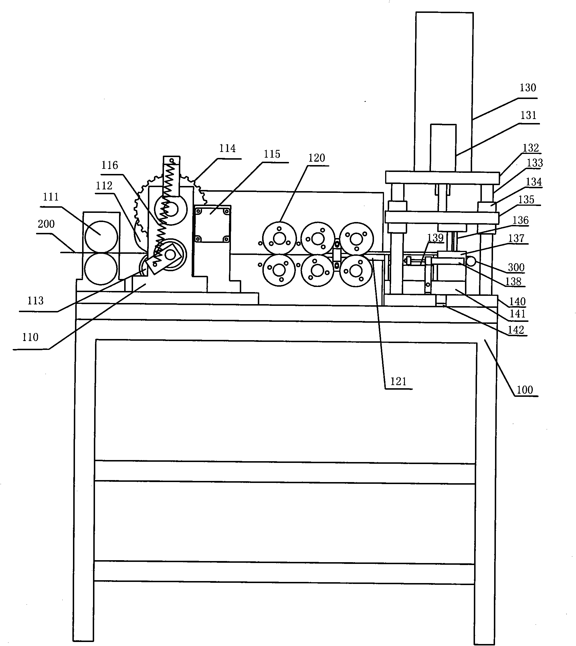
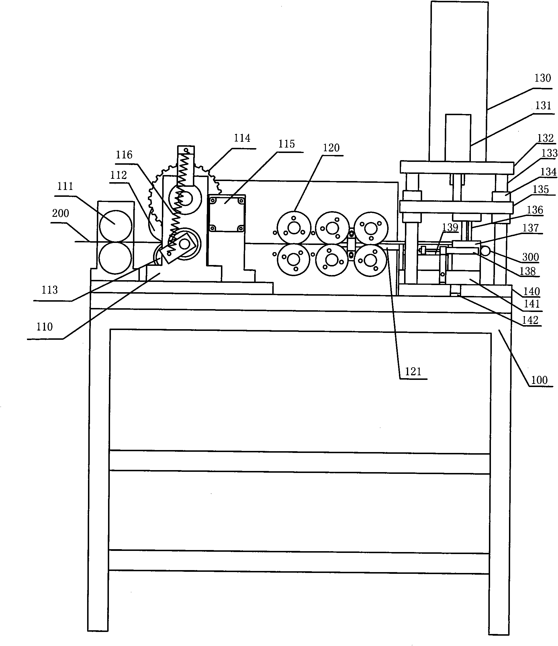
[0017] see figure 1 and figure 2 , the present invention provides an electromechanical combination device specially used for manufacturing constant force springs, that is, a computer numerical control constant force spring machine, including a base 100 and a forming mechanism, a feeding mechanism and a punching mechanism installed on the base 100; the forming mechanism , feeding mechanism and punching mechanism are controlled its operation by a PC control system, forming mechanism is installed at the rear end of base 100, feeding mechanism is installed at the output end of forming mechanism, and the output end of feeding mechanism is the front end of base and punching mechanism is installed. The strip material is stretched and formed by the form...


PUM


Abstract

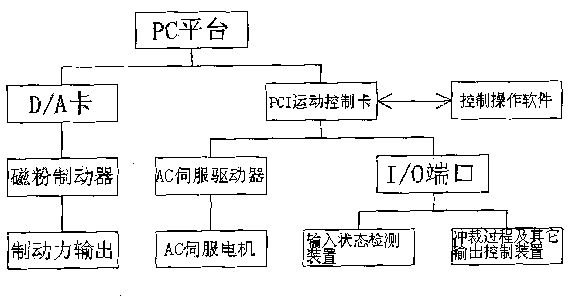
The invention discloses a computer numerical control constant force spring machine which is characterized by comprising a base, a forming mechanism, a feeding mechanism, a blanking mechanism and a PC control system, wherein the forming mechanism is used for carrying out stretch bending forming on the belting, and installed on the base; the feeding mechanism is used for conveying the belting and installed at the output end of the forming mechanism; the blanking mechanism is used for machining the butt end of the spring and installed at the output end of the feeding mechanism; and the PC control system is used for controlling the operation of the whole machine. The PC platform of the PC control system is a human-machine interaction interface, the program is compiled according to the product requirements, and finally, the signal is output by the control card to a servo driver; the servo driver controls an AC servomotor; and the AC servomotor drives the feeding mechanism and the forming mechanism, thereby achieving the goals of numerical control, automatic on-line size adjustment and continuous production of constant force springs. The invention can obviously enhance the production speed and precision of the constant force springs, reduce the labor intensity of the workers and enhance the production efficiency of the constant force springs.

Description

technical field [0001] The invention relates to an electromechanical combination device specially used for manufacturing constant force springs, in particular to a computer numerical control constant force spring machine for manufacturing constant force springs. Background technique [0002] Springs are commonly used components in the industry. Springs are used in various products ranging from aircraft and warships to mobile phones and cameras. The original spring is just a cylindrical tension and compression spring, which is wound by hand, the technology is relatively immature, and its production efficiency is low. With the gradual increase in the amount of springs, especially the widespread use of constant force springs, a number of companies producing spring equipment have emerged in countries such as Germany and Japan, and the technologies related to spring machines have gradually matured. Spring machines Now it has become a popular term, because the spring is not only ...

Claims


Application Information

Patent Timeline
IPC IPC(8): B21F35/00B21D43/00G05B19/18
Inventor 李峰
Owner TAIZHOU STRONKIN ELECTRONICS
Learn More