
Device for transposing inner boxes as irradiation containers for irradiation device and operation method thereof

An irradiation container and irradiation device technology, which is applied in the irradiation container inner box transposition device of the irradiation device and its operating field, which can solve the problem of dose waste, higher requirements for absorbed dose unevenness, irradiated products, high unevenness, etc. question

Inactive Publication Date: 2011-01-05
北京鸿仪四方辐射技术股份有限公司
View PDF4 Cites 0 Cited by
  • Summary
  • Abstract
  • Description
  • Claims
  • Application Information

AI Technical Summary

Problems solved by technology

[0004] The purpose of the present invention is to solve the problem that the irradiation device has too high unevenness when irradiating high-density products and causes dose waste, and that it cannot irradiate products with high requirements for absorbed dose unevenness. Irradiation container inner box transposition device and working method of the device

Method used


Image

  • Device for transposing inner boxes as irradiation containers for irradiation device and operation method thereof
  • Device for transposing inner boxes as irradiation containers for irradiation device and operation method thereof
  • Device for transposing inner boxes as irradiation containers for irradiation device and operation method thereof

Examples


Embodiment 1

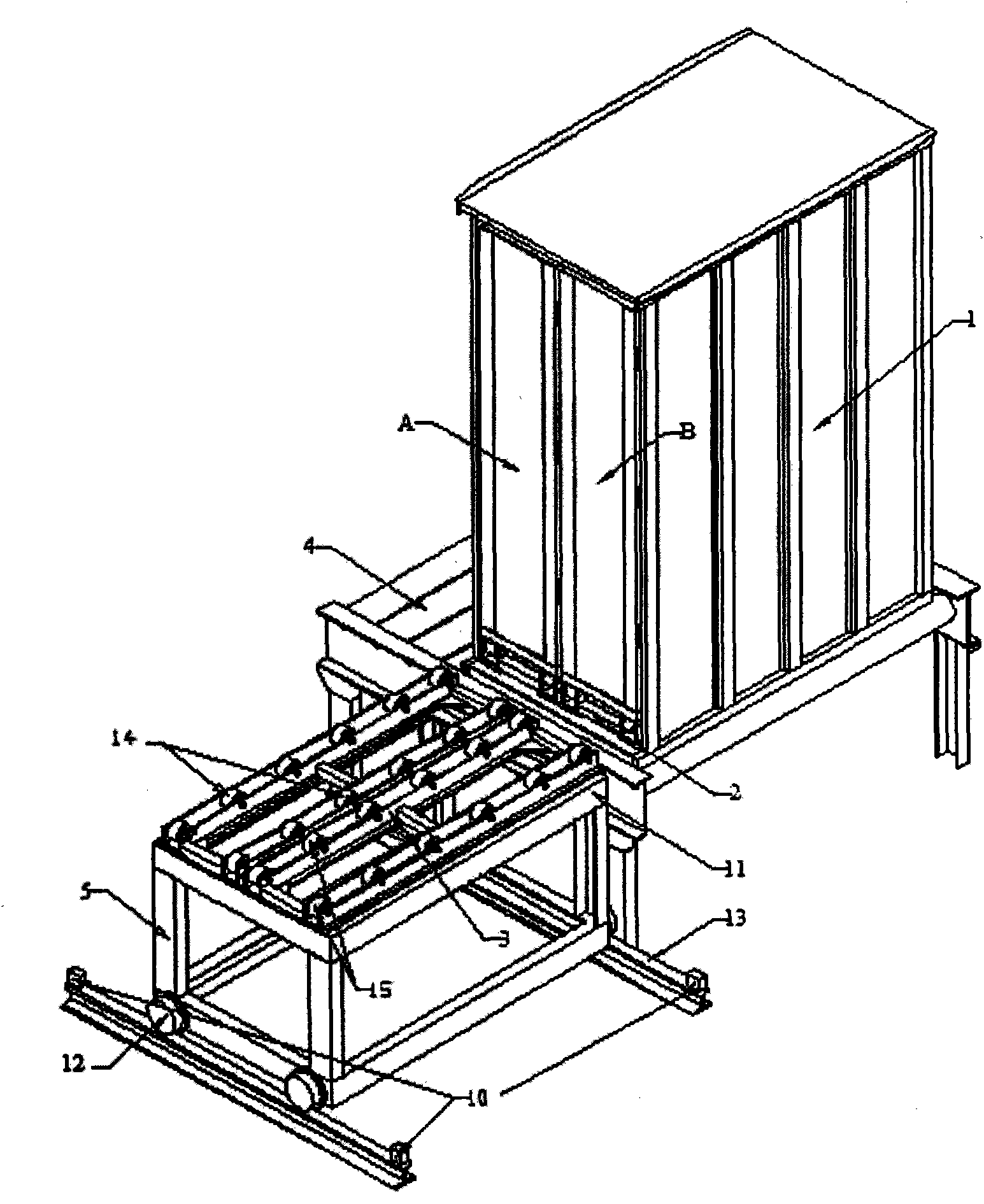
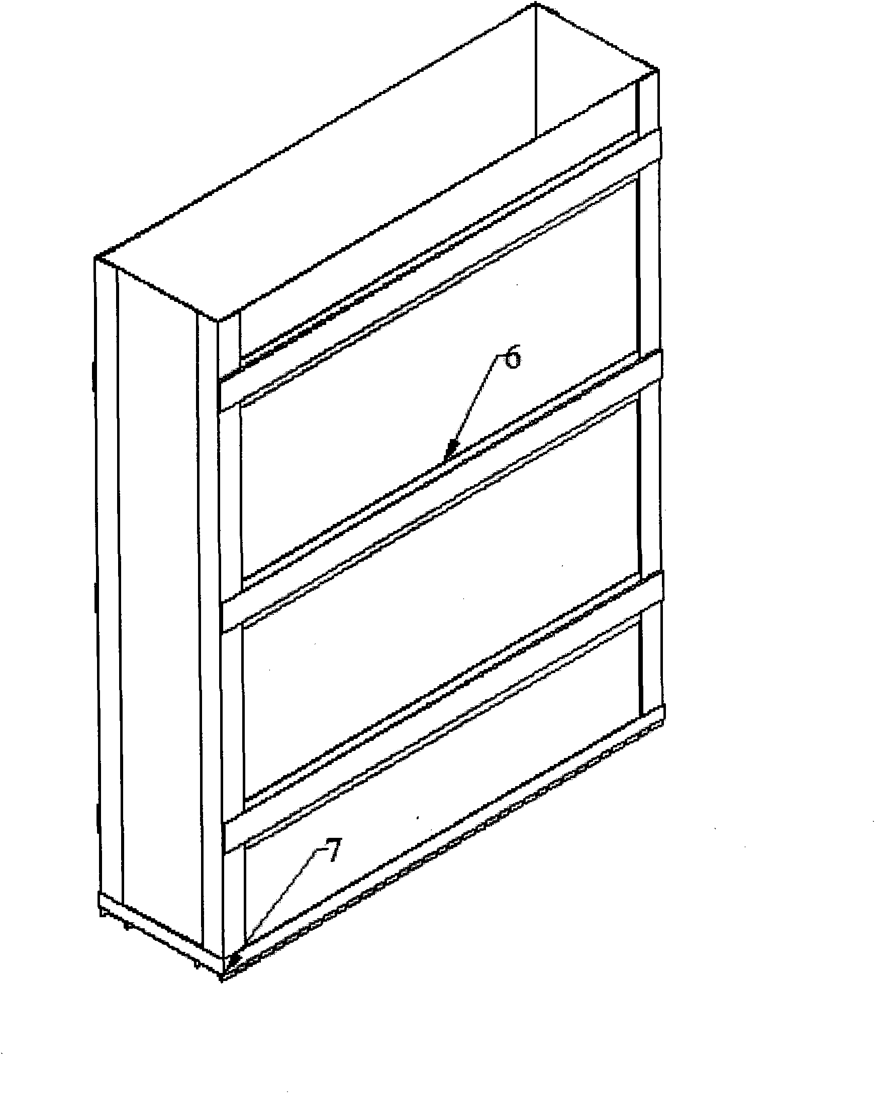
[0023] figure 1 Shown is the irradiation container inner box transposition device of the irradiation device of the present invention, including irradiation box 1, inner box A, inner box B, box inner support 2, box outer support 3, conveying device 4 and rail travel device 5, the irradiation box 1 is located on the conveying device 4, the inner box A and the inner box B are arranged in sequence on the box inner bracket 2 on the bottom surface of the irradiation box 1, and the box outer bracket 3 is located on the track moving device 5, and can move along the arrangement direction of the inner boxes A and B on the bottom surface of the irradiation box 1, and the inner boxes A and B can be supported on the inner support 2 and The box outer bracket 3 is vertically slid in the direction in which the inner boxes A and B are arranged.

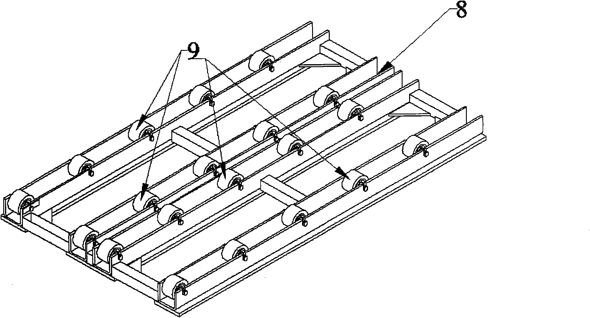
[0024] Such as figure 2 , 3 As shown, two roller ways 14, 15 are arranged at the corresponding positions of the two bottom edges of the inner box...

Embodiment 2

[0027] The difference between this embodiment and the irradiation container inner box transposition device of the above-mentioned irradiation device is that there are three inner boxes, and there are three sets of corresponding rollers on the inner box support and the outer box support.

[0028] Operation method of the irradiation container inner box transposition device of the irradiation device of the present invention

[0029] Such as Figure 4 As shown, the operation process is as follows:

[0030] (1) Place the two inner boxes in sequence in the irradiation box for irradiation;

[0031] (2) When the irradiation box 1 moves to the transposition position, the box inner bracket 2 is aligned with the box outer bracket 3 (see the transposition operation diagram figure 1 );

[0032] (3) Pull out the box body A and box body B from the irradiation box 1 to the bracket 3 outside the box (see the transposition operation diagram figure 2 );

[0033] (4) Move the track moving d...


PUM


Abstract

The invention provides a device for transposing inner boxes as irradiation containers for an irradiation device and an operation method thereof and aims to solve the problems that the irradiation device is prone to the excessively high non-uniformity and the waste of irradiation dose caused when irradiating high-density products and incapable of irradiating the products requiring higher non-uniformity of absorption dose. The device of the invention comprises a delivering device and an irradiation box located on the delivering device and is characterized by further comprising more than two inner boxes, supports inside and outside the irradiation box, and a rail traveling and moving device, wherein the inner boxes are sequentially arranged and located on the support inside the irradiation box on the bottom surface of the irradiation box; the support outside the irradiation box is located on the rail traveling and moving device in a way that the support outside the irradiation box can move in the direction of the inner boxes on the bottom surface of the irradiation box; and the inner boxes can slide in the direction perpendicular to the direction of the inner boxes on the supports inside and outside the irradiation box.

Description

technical field [0001] The invention relates to an irradiation device and an operation method thereof, in particular to an irradiation container inner box transposition device of the irradiation device and an operation method thereof. Background technique [0002] Modern large-scale irradiation devices mostly use standard irradiation boxes or spreaders to load irradiation products. Products are directly loaded into the irradiation box or spreader for irradiation. In order to increase the loading capacity of the irradiation device and improve the utilization rate of rays, the volume of the irradiation box or spreader is generally designed to be large. In the irradiation process, the relative position of the product in the standard irradiation box or spreader is fixed, and when the radiation interacts with the irradiated product, the energy is gradually consumed, the dose on the surface of the product is the largest, and the dose at the center of the product is the smallest. ...

Claims


Application Information

Patent Timeline
Patent Type & Authority Applications(China)
IPC IPC(8): G21K5/00G21K5/10
Inventor 宗慧奇旭松
Owner 北京鸿仪四方辐射技术股份有限公司
Learn More