
Process for soldering SiO2f/SiO2 composite ceramic and metal material

A technology of composite ceramics and metal materials, which is applied in the field of welding, can solve problems such as very large differences in thermal expansion coefficients, cracking of joints, lack of thermal stress, etc., and achieve the effect of reducing residual thermal stress and avoiding cracking

Active Publication Date: 2011-01-05
AVIC BEIJING INST OF AERONAUTICAL MATERIALS
View PDF1 Cites 19 Cited by
  • Summary
  • Abstract
  • Description
  • Claims
  • Application Information

AI Technical Summary

Problems solved by technology

[0003] SiO 2f / SiO 2 The connection of composite ceramics is generally suitable for brazing or diffusion welding methods, but direct SiO 2f / SiO 2 The bonding of composite ceramics to metals is very difficult because SiO 2f / SiO 2 The thermal expansion coefficients of composite ceramics and metals are very different (the former is about 0.3×10 -6 K -1 , the latter is generally about 5.5~15×10 -6 K -1 , that is, the difference is more than ten times or even dozens of times), which leads to the formation of huge residual thermal stress in the joint during the cooling process after high-temperature brazing or diffusion welding, which will directly cause the joint to peel off from the connection interface and crack. SiO 2f / SiO 2 For the connection of composite ceramics and metal materials, it is necessary to adopt a suitable method in this field to relieve the huge residual thermal stress formed in the connection joint after brazing or diffusion welding
About SiO 2f / SiO 2 For the connection of composite ceramics and metal materials, there is currently no effective method to relieve the residual thermal stress of the joint after welding

Method used


Image

  • Process for soldering SiO2f/SiO2 composite ceramic and metal material
  • Process for soldering SiO2f/SiO2 composite ceramic and metal material
  • Process for soldering SiO2f/SiO2 composite ceramic and metal material

Examples


Embodiment 1-4

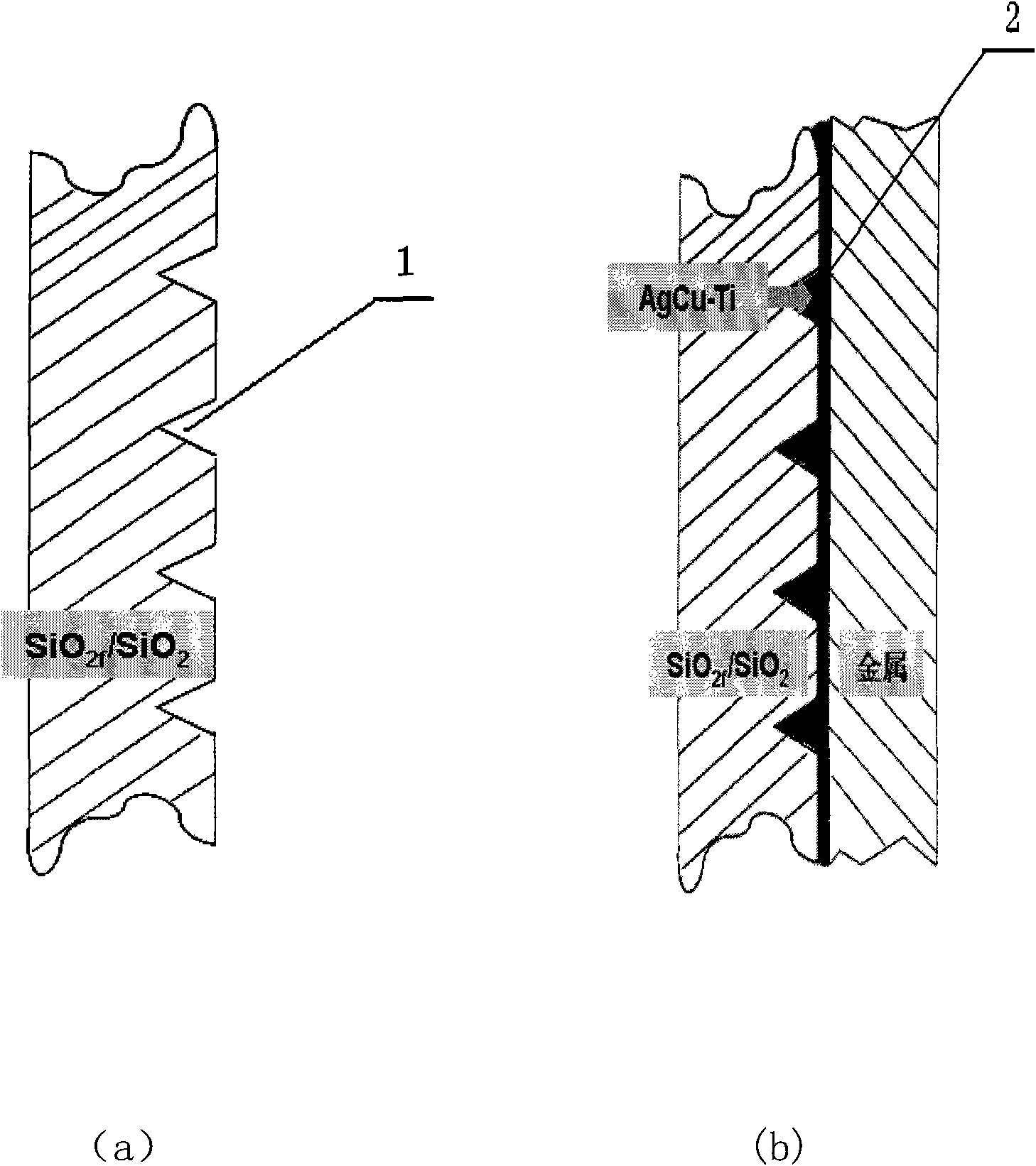
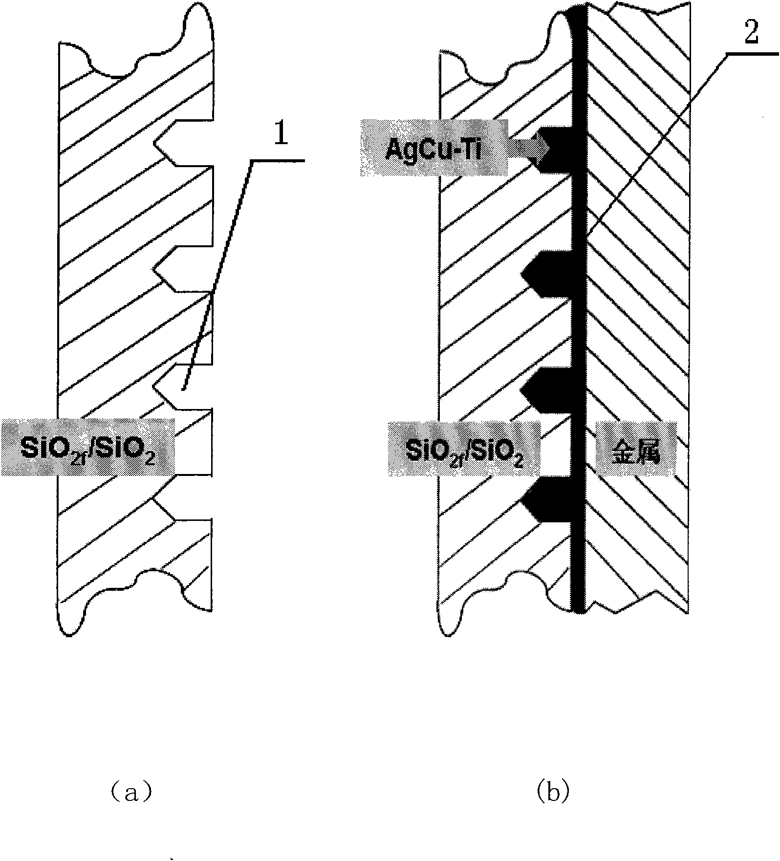
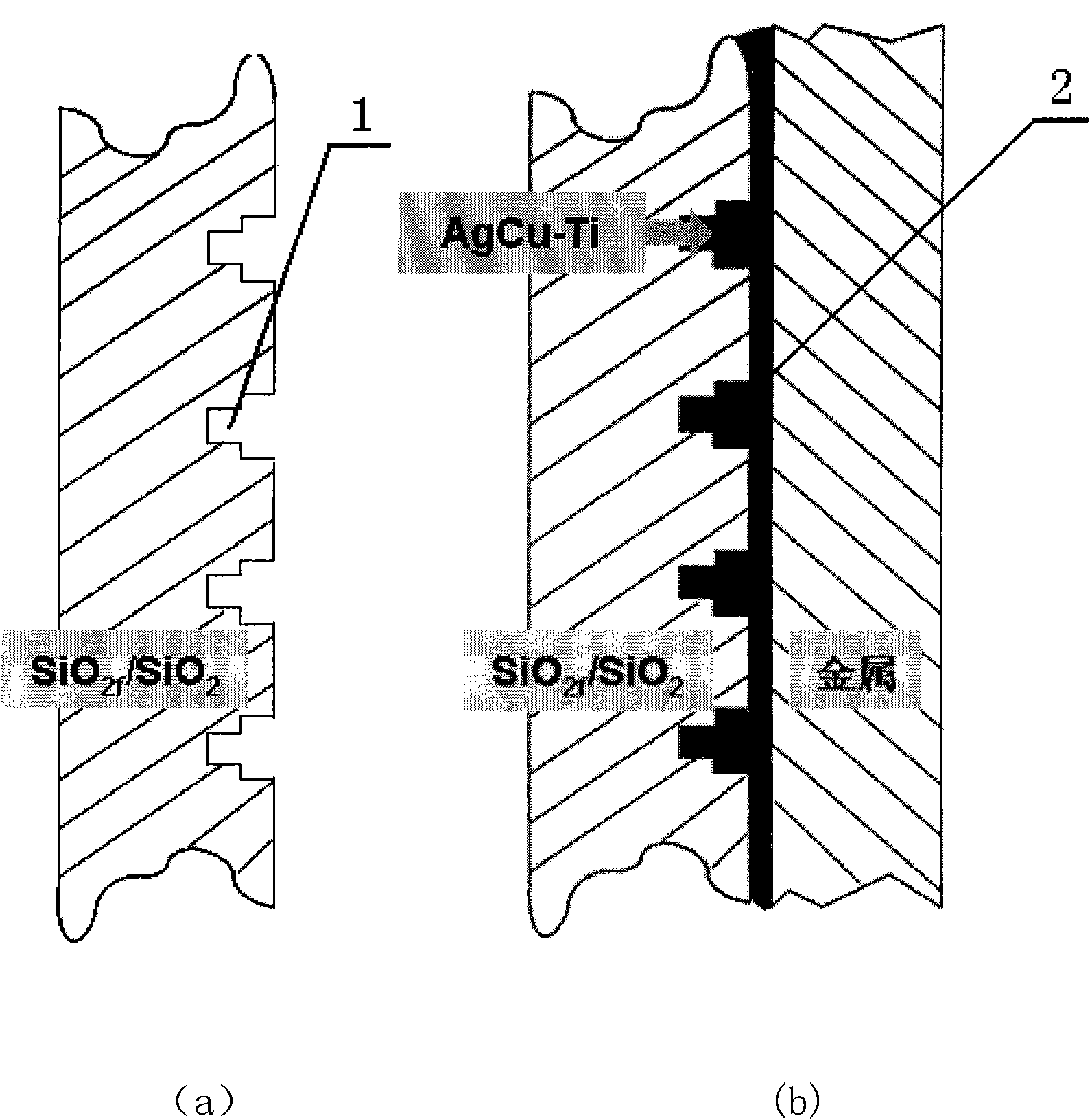
[0025] Respectively before welding by mechanical processing method on SiO 2f / SiO 2 The welded surface (plane) of the composite ceramics is grooved, and the grooves are parallel to each other, and the shape of the grooves corresponds to an approximate "V" groove (attached figure 1 ), approximately "U" shaped groove (attached figure 2 ), approximate "T" shaped slot (attached image 3 ), approximately straight groove (attached Figure 4 ). The surface width and depth of each groove are respectively 0.3mm-1.2mm and 1.0mm-3.5mm, and the interval between the grooves is 1.0mm-4.5mm.

[0026] Next, on SiO 2f / SiO 2 The groove on the surface of the composite ceramic to be welded and the welded SiO2 2f / SiO 2 The interface to be welded between composite ceramics and metal materials to be welded (4J36 alloy, TZM alloy, metal W, W alloy, metal Nb, Nb alloy, titanium alloy TC4, 18-8 stainless steel, GH783 alloy, 6H3044 alloy, GH4169 alloy) (Plane) are pre-prepared AgCu-Ti activ...

Embodiment 5

[0028] Before welding, the SiO 2f / SiO 2 The welded surface (annular surface) of the composite ceramics is grooved, and the grooves are distributed parallel to each other, and the shape of the grooves is an approximately straight groove (attached Figure 5 ). The surface width and depth of each groove are respectively 0.3mm-1.2mm and 1.0mm-3.5mm, and the interval between the grooves is 1.0mm-4.5mm.

[0029] Next, on SiO 2f / SiO 2 The groove on the surface of the composite ceramic to be welded and the welded SiO2 2f / SiO 2 The interface to be welded between composite ceramics and metal materials to be welded (4J36 alloy, TZM alloy, metal W, W alloy, metal Nb, Nb alloy, titanium alloy TC4, 18-8 stainless steel, GH783 alloy, GH3044 alloy, GH4169 alloy) (Annular surface) is pre-prepared AgCu-Ti active solder (Ti content between 1.4wt.% ~ 6.0wt.%), put it into a vacuum heating furnace together with the fixture after assembly, and heat it to 850 ° C ~ 910 ° C The brazing temp...

Embodiment 6

[0031] Respectively before welding by mechanical processing method on SiO 2f / SiO 2 The welded surface (plane) of the composite ceramics is grooved in two directions perpendicular to each other, and the grooves in the two directions are distributed parallel to each other, and the shape of each groove is an approximate "U" groove. The surface width and depth of each groove are 0.3mm-1.2mm and 1.0mm-3.5mm respectively, and the interval between the grooves is 1.0mm-4.5mm. Grooves are made in two directions perpendicular to each other, and all these grooves are distributed in a grid shape macroscopically. Next, on SiO 2f / SiO 2 The groove on the surface of the composite ceramic to be welded and the welded SiO2 2f / SiO 2 The interface to be welded between composite ceramics and metal materials to be welded (4J36 alloy, TZM alloy, metal W, W alloy, metal Nb, Nb alloy, titanium alloy TC4, 18-8 stainless steel, GH783 alloy, GH3044 alloy, GH4169 alloy) (Plane) are pre-prepared Ag...


PUM


Abstract

The invention discloses a process for soldering a SiO2f / SiO2 composite ceramic and a metal material, which is characterized by selecting AgCu-Ti active solder to connect the SiO2f / SiO2 composite ceramic, and by comprising the following process steps: making grooves on the to-be-soldered surface of the SiO2f / SiO2 composite ceramic by a machining process; placing the active solder in the grooves on the to-be-soldered surface of the SiO2f / SiO2 composite ceramic and adding the AgCu-Ti solder on the to-be-soldered interface between the soldered SiO2f / SiO2 composite ceramic and the soldered metal material; and realizing the effective connection of the SiO2f / SiO2 composite ceramic and the metal material by vacuum soldering and heating.

Description

technical field [0001] The invention belongs to the field of welding technology, and relates to a 2f / SiO 2 A process for brazing composite materials and metal materials. Background technique [0002] Quartz fiber reinforced quartz composite ceramics (SiO 2f / SiO 2 ) is a promising high-temperature structural ceramic matrix composite. However, due to the special requirements for the combination of performance in some engineering applications, it is necessary to form a composite structure with metal materials for application. [0003] SiO 2f / SiO 2 The connection of composite ceramics is generally suitable for brazing or diffusion welding methods, but direct SiO 2f / SiO 2 The bonding of composite ceramics to metals is very difficult because SiO 2f / SiO 2 The thermal expansion coefficients of composite ceramics and metals are very different (the former is about 0.3×10 -6 K -1 , the latter is generally about 5.5~15×10 -6 K -1 , that is, the difference is more than...

Claims


Application Information

Patent Timeline
Patent Type & Authority Applications(China)
IPC IPC(8): C04B37/02
Inventor 熊华平陈波程耀永李晓红毛唯
Owner AVIC BEIJING INST OF AERONAUTICAL MATERIALS
Learn More