Eureka AIR delivers breakthrough ideas for toughest innovation challenges, trusted by R&D personnel around the world.

Mixing agitator for materials

A technology for mixing and mixing materials, applied in mixers, mixing methods, mixers with rotating agitating devices, etc., can solve problems such as high operating costs, unsatisfactory, dust pollution, etc., and achieve improved mixing uniformity and long service life , Stir strong effect

Inactive Publication Date: 2011-01-05
江苏诚德钢管股份有限公司
View PDF3 Cites 4 Cited by
  • Summary
  • Abstract
  • Description
  • Claims
  • Application Information

AI Technical Summary

Problems solved by technology

At present, traditional processes such as pickling and shot blasting are commonly used in domestic descaling. The waste acid and waste gas produced by pickling seriously pollute the environment, and are increasingly restricted by the national environmental protection.
The dust pollution caused by shot blasting is also very serious, and the surface of the steel pipe is deformed with many pits, which requires a large investment in equipment and high operating costs.
The cold stainless steel / carbon steel wire, bar and strip steel high-pressure water shot peening descaling method of Hangzhou Iron and Steel Group Co., Ltd. and the metal wire or bar abrasive water jet descaling method and equipment of Hunan Nonferrous Heavy Machinery Co., Ltd. are The high-pressure water mixture is sprayed onto the surface of the steel, which is mainly used for descaling the outer surface of wire rods, rods and other products. In the production process of seamless steel pipes, the oxide skin on the inner surface of the steel pipes due to heat treatment cannot be removed, so that it cannot be removed. Meet the requirements of the next cold drawing process

Method used


Image

  • Mixing agitator for materials
  • Mixing agitator for materials

Examples


Embodiment Construction

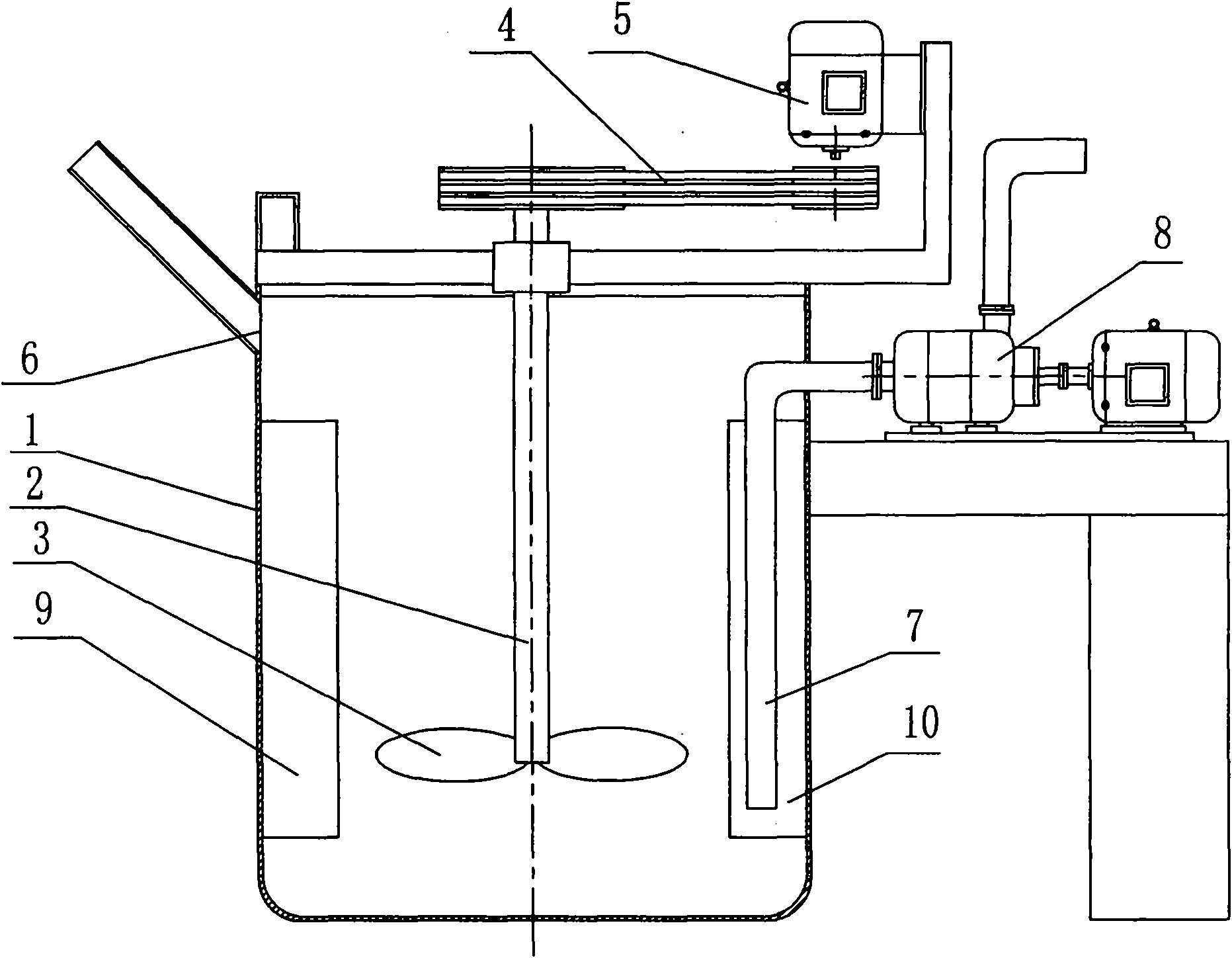
[0009] Such as figure 1 As shown, the present invention is provided with a barrel body 1, a stirring shaft concentrically arranged vertically with the barrel body 1, the lower end of the stirring shaft 2 in the barrel body 1 is connected to the blade 3, and the stirring shaft 1 outside the barrel body 1 passes through a transmission reduction mechanism 4 is connected with the motor 5 that is arranged on the outside of barrel body 1.

[0010] A feed inlet 6 is arranged at the upper end of the barrel body 1, and a suction pipe 7 is arranged inside the barrel body 6. The upper end of the material suction pipe 7 is connected with the inlet end of the water pump 8 arranged outside the barrel body 1, and is symmetrically fixed on the inner wall of the barrel body 1. Connect two vertical deflectors 9,10, the lower end of each deflector 9,10 is located below the horizontal plane of the blade 3, and the inlet end of the suction pipe 7 is arranged between the lower end of the deflector ...


PUM


Abstract

The invention discloses a mixing agitator for materials and relates to the technical field of material mixers. A blade is connected at the lower end of an agitating shaft in a barrel; the agitating shaft is connected with a motor arranged outside the barrel body through a transmission speed-reducing mechanism; a feed port is formed at the upper end of the barrel body; a suction tube is arranged inside the barrel body; the upper end of the suction tube is connected with an inlet end of a water pump arranged outside the barrel body; two vertical guide plates are symmetrically and fixedly connected to an inner wall of the barrel body; the lower ends of the vertical guide plates are positioned below the horizontal plane of the blade; and an inlet end of the suction tube is arranged between the lower ends of the vertical guide plates and the horizontal plane of the blade. Slurry can generate omega-shaped and circumferential convective motion in the barrel body, fluid circumferentially shears convective circulation up and down, and the slurry is uniformly dispersed. The mixing agitator for materials has the characteristics of low energy consumption, uniform dispersion, strong agitation, long service life of an agitating wheel, no solid-phase settlement and the like, capacity of improving mixing uniformity of scale removing sand and water, and contribution to scale removal for steel pipes.

Description

technical field [0001] The invention relates to the technical field of material mixers. Background technique [0002] With the acceleration of my country's seamless steel pipe production speed and the continuous expansion of construction scale, its production equipment and production technology have made great progress, but compared with some developed countries, there are still many shortcomings, some old equipment and traditional production technology are facing challenges. [0003] During the heating process of the seamless steel pipe, the oxygen, carbon dioxide, moisture, etc. in the furnace gas react and diffuse with the iron element in the steel surface layer, and a large amount of oxide scale is formed on the surface. For the next cold drawing process, the surface oxide skin should be removed, that is, the steel pipe descaling technology. At present, traditional processes such as pickling and shot blasting are commonly used in domestic descaling. The waste acid and w...

Claims


Application Information

Patent Timeline
Patent Type & Authority Applications(China)
IPC IPC(8): B01F7/20B01F3/12B21C43/02B01F27/906
Inventor 王林林施军罗伟
Owner 江苏诚德钢管股份有限公司
Why Eureka
Eureka Blog
Learn More