
Double-ball valve motorcycle fuel steam acquisition system

A fuel vapor and collection system technology, which is applied to the charging system, adding non-fuel substances to fuel, engine components, etc., can solve problems such as failure of fuel vapor adsorption, loss of fuel vapor collection function, and impact on service life. Simple, low cost, fuel saving effect

Inactive Publication Date: 2011-12-14
力帆科技(集团)股份有限公司
View PDF0 Cites 0 Cited by
  • Summary
  • Abstract
  • Description
  • Claims
  • Application Information

AI Technical Summary

Problems solved by technology

[0003] Although the fuel vapor in the fuel tank enters the carbon tank after being collected, and is absorbed by the carbon tank and then enters the engine for use, which achieves a certain fuel-saving effect, but there are still the following deficiencies: the traditional anti-roll valve is installed outside the fuel tank. Only when the car body is completely dumped can it play an anti-tilt role, and because the valve body is generally made of plastic, it is easy to damage
When the motorcycle rolls or the road conditions are bumpy when driving, the fuel tank tilts too much so that the collection port of the fuel vapor collection pipe is submerged in the fuel, causing the fuel in the fuel tank to directly enter the fuel vapor collection pipe. When the motorcycle is reset, it enters The fuel in the fuel vapor collection pipe will enter the anti-dump valve and pass through the air passage in it to finally flow into the carbon tank. After the carbon tank is supersaturated with fuel, not only the temperature rises sharply, which seriously affects its service life, but also makes its fuel vapor adsorption function invalid. , the fuel will also leak out through the vent hole set at the bottom of the carbon tank, and at the same time, some fuel may remain in the collection system and cause pipeline blockage, resulting in the loss of the fuel vapor collection function

Method used


Image

  • Double-ball valve motorcycle fuel steam acquisition system
  • Double-ball valve motorcycle fuel steam acquisition system
  • Double-ball valve motorcycle fuel steam acquisition system

Examples


Embodiment Construction

[0020] The present invention will be described in further detail below in conjunction with the accompanying drawings and specific embodiments.

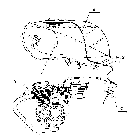
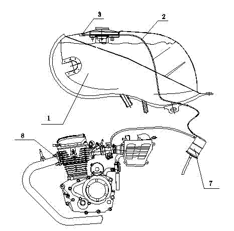
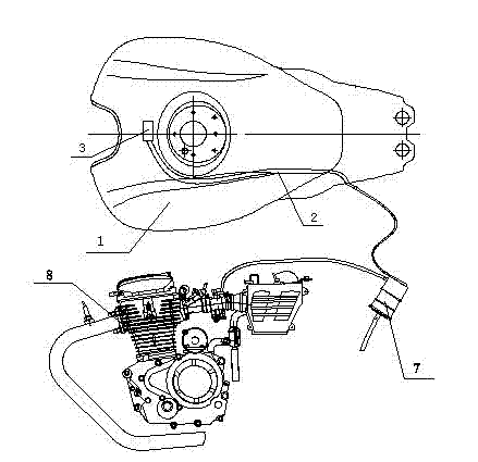
[0021] Such as figure 2 , image 3 , Figure 4 and Figure 5 As shown, a double ball valve type motorcycle fuel vapor collection system includes a fuel tank 1, an anti-dump valve 3, a fuel vapor collection pipe 2 and a carbon tank 7. The anti-dump valve 3 is horizontally arranged in the fuel tank 1 and welded and fixed on the fuel tank 1. On the inner top wall of the fuel vapor collection pipe 2, the fuel vapor collection pipe 2 is welded and fixed on the inner wall of the fuel tank 1 and passes through the fuel tank body to connect with the carbon canister 7. The collection pipe 2 is a metal pipe; The rear end of the valve 3 is fixedly connected to the collection port at the front end of the steam collection pipe 2 . The anti-roll valve 3 includes a top plate and a bottom plate structure, the top plate is a plane plate, and the ...


PUM


Abstract

The invention discloses a double-ball valve motorcycle fuel steam acquisition system which comprises a fuel tank, a steam acquisition pipe, an anti-sway valve and a charcoal canister. The system is characterized in that the anti-sway valve is arranged in the fuel tank and is fixedly installed on the top of the fuel tank, the back end of the anti-sway valve is connected with the front end of the steam acquisition pipe, the front end refers to a steam acquisition port of the steam acquisition pipe, the anti-sway valve is communicated with the steam acquisition pipe, the steam acquisition pipe goes out of the tank body of the fuel tank and is connected with and communicated with the charcoal canister, and the anti-sway valve is of a double ball type. The system has the advantages of simple structure and low cost, can prevent fuel from flowing into the fuel steam acquisition pipe, ensures that the acquisition pipe can normally acquire the fuel steam and the charcoal canister has a normal adsorption effect, and has the characteristics of reliable operation and long service life.

Description

technical field [0001] The invention belongs to the technology used on motorcycles, and in particular relates to a double ball valve type motorcycle fuel vapor collection system for motorcycles. Background technique [0002] At present, most motorcycle fuel vapor collection systems include fuel tanks, fuel vapor collection pipes, adsorption pipes, and carbon canisters. Fuel vapor collection pipes are generally made of corrosion-resistant metal materials, such as copper, and their front ends are fixed on the top of the fuel tank. Such as figure 1 As shown, the fuel vapor collection pipe 2 is fixed in the fuel tank by welding its front end to the top of the fuel tank 1. The front end of the collection pipe 2 is the fuel vapor collection port. Because it is close to the top wall of the fuel tank, when the motorcycle is working normally Can always be above the fuel liquid level, the lower end of the fuel vapor collection pipe 2 passes through the tank body of the fuel tank 1 an...

Claims


Application Information

Patent Timeline
Patent Type & Authority Patents(China)
IPC IPC(8): F02M25/08
Inventor 马文选张恒
Owner 力帆科技(集团)股份有限公司
Learn More