Eureka AIR delivers breakthrough ideas for toughest innovation challenges, trusted by R&D personnel around the world.

Ampoule scoring machine

A scoring machine and ampoule technology, which is applied in glass manufacturing equipment, glass cutting devices, manufacturing tools, etc., can solve the problems of small ampoule breaking force, achieve small ampoule breaking force, reduce particle and microbial contamination, and facilitate clinical work. Effect

Inactive Publication Date: 2010-12-22
向永川
View PDF0 Cites 8 Cited by
  • Summary
  • Abstract
  • Description
  • Claims
  • Application Information

AI Technical Summary

Problems solved by technology

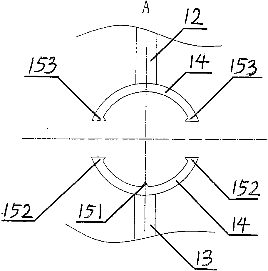
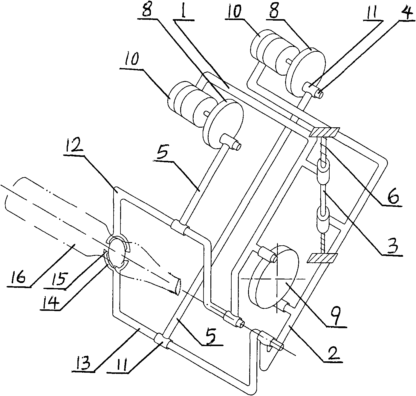
[0003] The purpose of the present invention is to solve the defects of the structure and function of the existing ampoule scoring machine, to provide an ampoule scoring machine capable of controlling the breaking force of the ampoule, which increases the scoring functions and capabilities of the ampoule, and obtains the ampoule breaking force produced Smaller, it can be opened by hand or easily opened with ampoule opening pliers (application number: 200820075401.3), which brings convenience to medical staff to open ampoules, reduces scratches on the grinding wheel of scored ampoules and disinfection with alcohol swabs, and improves ampoule packaging. Hygienic and safe level of water injection medication

Method used


Image

  • Ampoule scoring machine
  • Ampoule scoring machine
  • Ampoule scoring machine

Examples


Embodiment Construction

[0011] specific implementation plan

[0012] The present invention will be described in further detail below in conjunction with the accompanying drawings and specific embodiments.

[0013] Explanation of the main structure and details in the accompanying drawings:

[0014] 1——upper moving frame 2——lower moving frame 3——sliding frame 4——shaft

[0015] 5——Connecting Rod 6——Spring 7——Linkage Crank 8——Crank

[0016] 9——linkage cam 10——electric motor 11——shaft sleeve 12——upward moving tool rest

[0017] 13——Down moving knife holder 14——Slider 15——Knife tip 16——Ampoule

[0018] 151——Main scoring tip 152——Secondary scoring tip 153——Side scoring tip

[0019] Such as figure 1 , figure 2 , image 3 with Figure 4 As shown, the ampoule scoring machine of the present invention consists of an upper moving frame 1, a lower moving frame 2, a sliding frame 3, a shaft 4, a connecting rod 5, a spring 6, a linked crank 7, a crank 8, a linked cam 9, a motor 10, and an axle sleeve 11. T...


PUM


Abstract

The invention discloses an ampoule scoring machine, which comprises an upper moving frame, a lower moving frame, a sliding frame, shafts, connecting rods, springs, a connecting rod frame, a linkage crank, cranks, a linkage cam, electromotors, shaft sleeves, an upper moving tool rest, a lower moving tool rest, a slider and a tool nose, wherein the upper moving frame and the lower moving frame are connected through the shafts or the sliding frame and slide up and down under the rotation of the linkage cam and the action of the springs or swing up and down under the rotation of the linkage crank and the action of the springs, the shaft sleeves are arranged on the upper moving frame and the lower moving frame, and the upper moving tool rest and the lower moving tool rest are arranged in the shaft sleeves; and the slider is fixed on the upper moving tool rest and the lower moving tool rest, and the tool nose is fixed on the slider. The upper moving tool rest and the lower moving tool rest are respectively connected with one connecting rod, the connecting rods are connected with the cranks which are fixed with the rotation shafts of the electromotors, and the electromotors are fixed on the upper moving frame and the lower moving frame. The ampoule scoring machine can control the magnitude of fracture strength of an ampoule to obtain decreased fracture strength of the produced ampoule, thereby bringing convenience for the medical staff to open ampoules.

Description

technical field [0001] The invention relates to an ampoule scoring machine for an ampoule production line, which belongs to the technical fields of mechanical mechanism and production linkage technology of the production line and pharmaceutical packaging production. Background technique [0002] The ampoule scoring machine in the existing production line adopts straight knife-edge reciprocating scoring or circular knife-edge rotary scoring. The arc length of the notch is proportional to the depth, resulting in poor controllability of the breaking force of the ampoule, and the number of notches is limited, and the breaking force of the notched ampoule is too large, which often leads to leakage of the drug solution after the ampoule is filled. The notch ampoules in the prior art are not easily folded, which brings great inconvenience to the clinical operation, causing serious violations of the opening operation of the ampoules, and causing hidden dangers in drug safety. The m...

Claims


Application Information

Patent Timeline
Patent Type & Authority Applications(China)
IPC IPC(8): C03B33/06
Inventor 向永川
Owner 向永川
Why Eureka
Eureka Blog
Learn More