
Airplane external illuminating space angle-positioning combining equipment

A technology of external lighting and spatial angle, which is applied to measurement devices, instruments, optical devices, etc., can solve the problems of difficulty in positioning the spatial angle on the plane, unable to obtain the real data of the product, and difficult on-board testing and testing, so as to reduce the test guarantee requirements, The effect of reducing the difficulty of test debugging and reducing test costs

Active Publication Date: 2010-12-01
XIAN AIRCRAFT DESIGN INST OF AVIATION IND OF CHINA
View PDF4 Cites 16 Cited by
  • Summary
  • Abstract
  • Description
  • Claims
  • Application Information

AI Technical Summary

Problems solved by technology

[0002] At present, the on-board test of the aircraft's external lighting system can only complete part of the test, such as the landing light system, emergency lights, etc.; due to the complexity of the test angle for some lighting systems such as navigation lights and anti-collision lights, it is difficult to locate the space angle on the plane , The difficulty of testing makes it difficult to carry out on-board testing. Only the laboratory test data of a single lighting fixture can be used as a reference, and the real data after the product is installed cannot be obtained.

Method used


Image

  • Airplane external illuminating space angle-positioning combining equipment
  • Airplane external illuminating space angle-positioning combining equipment
  • Airplane external illuminating space angle-positioning combining equipment

Examples


Embodiment Construction

[0014] The present invention will be described in detail below with reference to the drawings and embodiments.

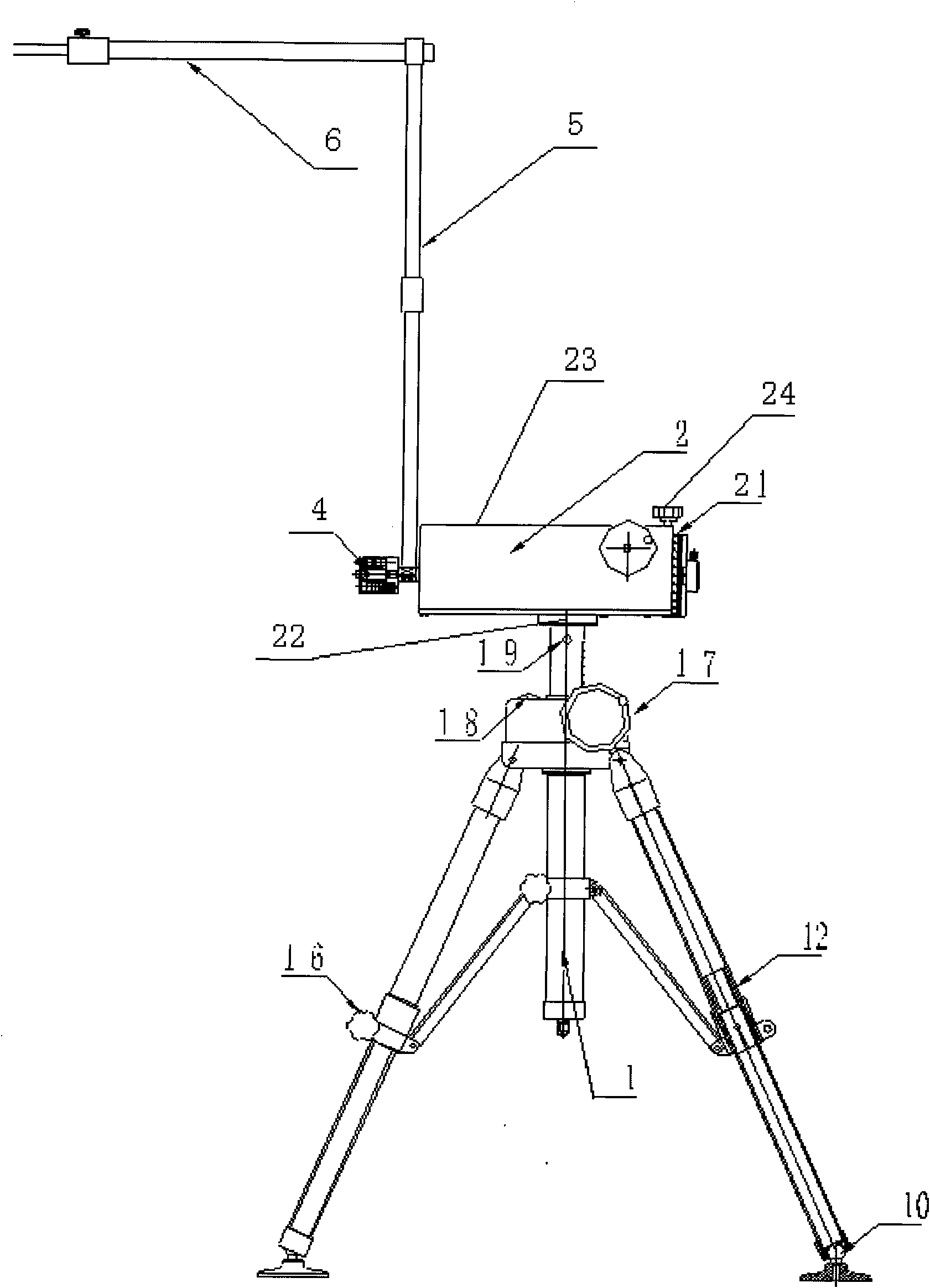
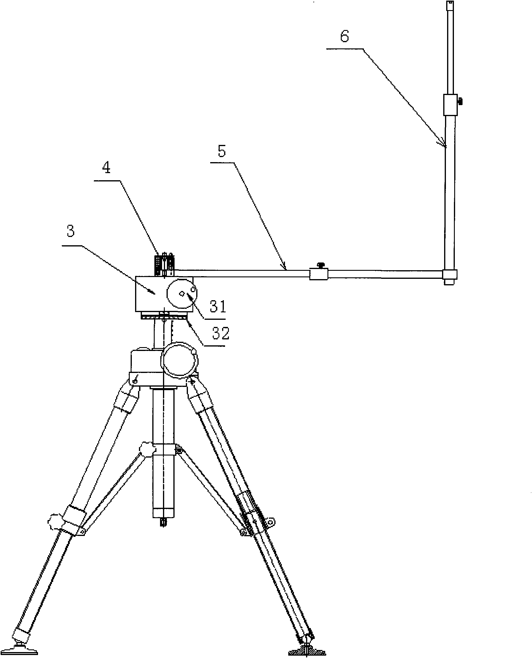
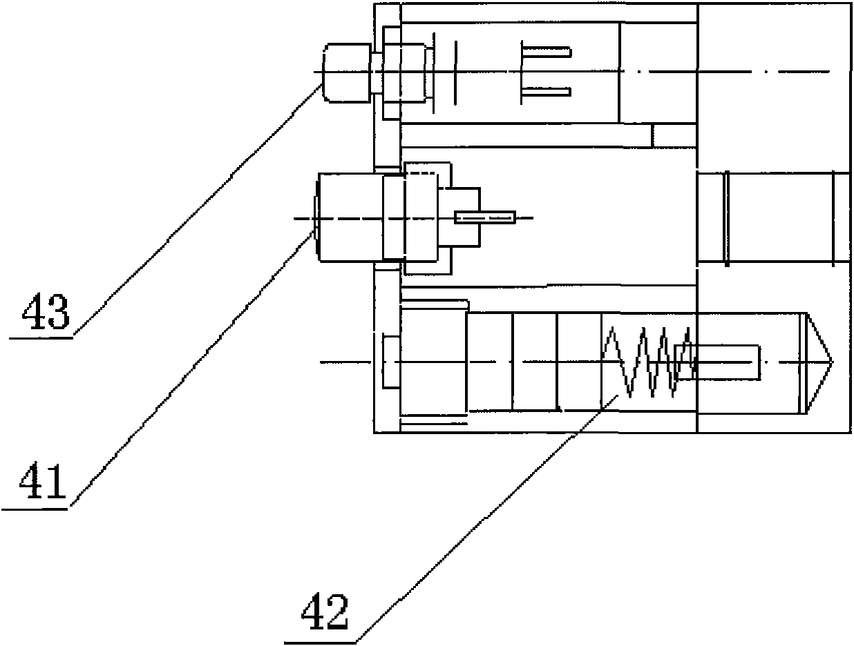
[0015] In this embodiment, the aircraft exterior lighting space angle positioning combination equipment includes a tripod 1, a vertical measurement turntable 2, a horizontal measurement turntable 3, a laser 4, a main test rod 5, and a secondary test rod 6;

[0016] Among them, the tripod is made of aluminum alloy, the legs 12 are of two-section structure, which can be retracted and retracted, and the two legs are equipped with locking handles. 16 pairs of telescopic pull-out tripod legs are locked in position, suitable for rough adjustment of the tripod height and the whole tripod. Leveling; the legs and feet are equipped with universal joint leg support feet 10 to ensure that the tripod is stable and reliable; the central axis adopts a turbine worm structure, the handwheel 17 swings and rises, and the position is self-locking to achieve precise adjustment of the height o...


PUM


Abstract

The invention discloses airplane external illuminating space angle-positioning combining equipment which comprises a tripod (1), a vertical measurement rotating platform (2), a horizontal measurement rotating platform (3), lasers (4), a main measuring rod (5) and an auxiliary measuring rod (6), wherein the tripod can carry out position self locking to realize the height rough adjustment and accurate adjustment of the tripod; a central shaft of the tripod is butted with the vertical measurement rotating platform and the horizontal measurement rotating platform by ejecting screws (19); the lasers are installed at the top ends of central shafts of the vertical measurement rotating platform and the horizontal measurement rotating platform for realizing the alignment of shaft centers of the rotating platforms and a shaft center of a lamp to be measured; the main measuring rod is installed on a rotating platform central shaft, and the auxiliary measuring rod is installed at the other end of the main measuring rod and forms an included angle of 90 degrees with the main measuring rod; the top of the other end of the auxiliary measuring rod is provided with a measuring probe; and the measuring rods rotate by adopting the lamp to be measured as a center along with the rotating platform central shaft for carrying out measurement angle positioning on the lamp to be measured. The combining equipment of the invention realizes the on-board test of the external illuminating lamp needing positioning a space angle, is convenient for carrying out an outfield test and reduces the test guarantee demand and the test cost.

Description

Technical field [0001] The invention belongs to lighting testing technology. Background technique [0002] At present, the on-board test of the aircraft's external lighting system can only complete part of the tests, such as landing light systems, emergency lights, etc.; for navigation lights, anti-collision lights and other lighting systems that require spatial angle testing, the test angle is complex, and the on-board space angle positioning is difficult , The test difficulty is high, which makes it difficult to carry out the on-board test test. The laboratory test data of a single lighting fixture can only be used as a reference, and the real data after the product is installed cannot be obtained. Summary of the invention [0003] The purpose of the present invention is to design a universal aircraft external lighting test equipment to achieve on-board testing of external lighting fixtures that need to be positioned at a spatial angle; the system is portable, convenient for fie...

Claims


Application Information

Patent Timeline
Patent Type & Authority Applications(China)
IPC IPC(8): G01B11/26G01B11/27
Inventor 李七五田玉斌王建军
Owner XIAN AIRCRAFT DESIGN INST OF AVIATION IND OF CHINA
Learn More