Control device of engine, control device of engine and hydraulic pump, and control device of engine, hydraulic pump, and generator motor
A technology of generator motor and control device, applied in engine control, electrical control, machine/engine, etc., can solve the problems of pump efficiency, fuel consumption and noise deterioration, etc.
- Summary
- Abstract
- Description
- Claims
- Application Information
AI Technical Summary
Problems solved by technology
Method used
Image
Examples
no. 1 Embodiment
[0164] First, the first embodiment will be described.
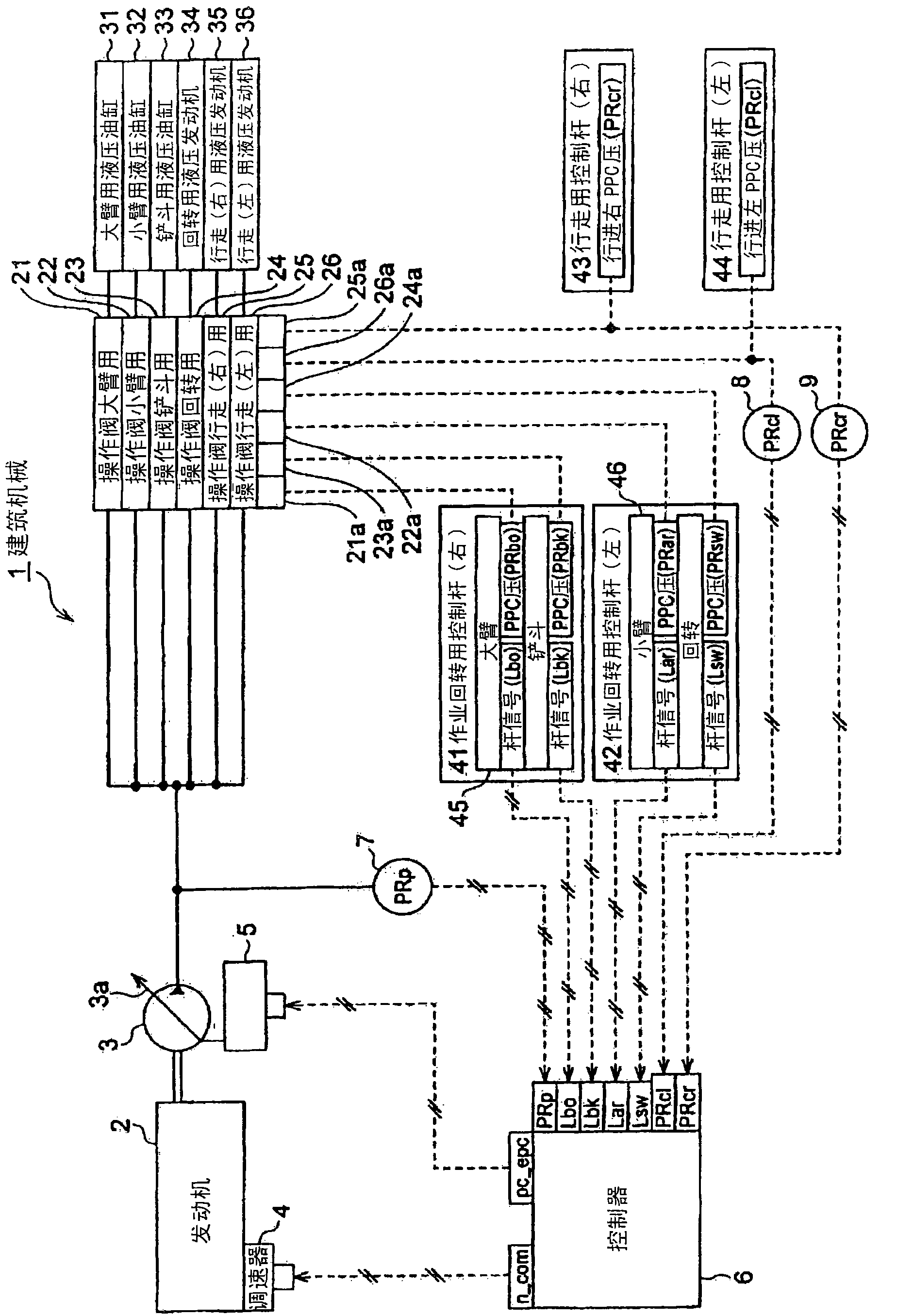
[0165] The first embodiment takes figure 1 The configuration example shown is a premise. Figure 4 , Figure 6 It is a control block diagram showing the processing content performed by the controller 6 .
[0166] Such as Figure 4 As shown, the hydraulic actuator target flow rate calculation unit 50 calculates the value of The corresponding target flow rate Qbo of the hydraulic cylinder 31 for the boom, the target flow rate Qar of the hydraulic cylinder 32 for the support arm, the target flow rate Qbk of the hydraulic cylinder 33 for the bucket, the target flow rate Qsw of the hydraulic cylinder 34 for the swing, and the target flow rate Qsw of the hydraulic cylinder 34 for the right travel The target flow rate Qcr of the cylinder 35 and the target flow rate Qcl of the hydraulic cylinder 35 for left travel.
[0167] The functional relationship 51a, 52a, 53a, 54a, 55a, 56a between the operation amount of each hydrauli...
no. 2 Embodiment
[0237] Next, a second embodiment will be described.
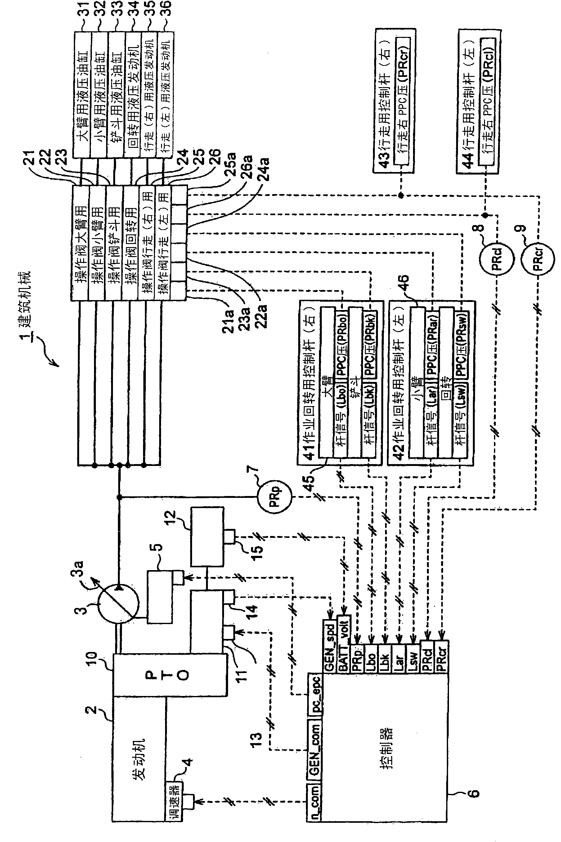
[0238] The structure of the construction machine 1 of the second embodiment is as follows: image 3 Assuming the configuration example shown, and figure 1 Compared with the configuration example of the above, a PTO shaft 10, a generator motor 11, an accumulator 12, an inverter 13, a rotation sensor 14, and a voltage sensor 15 are added, and the generator motor 11 functions as a motor and generates electricity.
[0239] Figure 5 , Figure 6 , Figure 7 , Figure 8 It is a control block diagram showing the processing content performed by the controller 6 .
[0240] Figure 5 is the same as that of the first embodiment Figure 4 corresponding figure, with Figure 4 The description of the repeated part is omitted.
[0241] Such as Figure 5 , Figure 6 As shown, the second embodiment is the same as the first embodiment, when the minimum value selector 65 selects the target engine speed ncom, then, below, switch to ...
no. 3 Embodiment
[0327] In the above-mentioned second embodiment, the description has been made on the premise that the hydraulic swing system rotates the upper swing body of the construction machine 1 by the hydraulic actuator (hydraulic motor). Next, a second embodiment will be described on the premise of an electric swivel system that swivels the upper swivel body of the construction machine 1 with a hydraulic actuator.
[0328] Figure 15 It is a configuration diagram of the third embodiment, showing the configuration of a construction machine 1 equipped with an electric rotating system.
[0329] as Figure 15 shown, with image 3 has the same composition as figure 1 Compared with the first embodiment, a generator motor 11, a battery 12, an inverter 13, a rotation sensor 14, and a voltage sensor 15 are added. The case where the generator motor 11 performs the motoring and generating functions is the same, and the components for rotating the upper revolving body through the electric act...
PUM
 Abstract
Description
Claims
Application Information
 - Generate Ideas
- Intellectual Property
- Life Sciences
- Materials
- Tech Scout
- Unparalleled Data Quality
- Higher Quality Content
- 60% Fewer Hallucinations
Browse by: Latest US Patents, China's latest patents, Technical Efficacy Thesaurus, Application Domain, Technology Topic, Popular Technical Reports.
© 2025 PatSnap. All rights reserved.Legal|Privacy policy|Modern Slavery Act Transparency Statement|Sitemap|About US| Contact US: help@patsnap.com


