Grid drive circuit for controlling bridge type drive circuit

A gate drive circuit and drive circuit technology, applied in the direction of electrical components, output power conversion devices, etc., can solve the problems of large characteristic size of gate drive chips, large area occupied by gate drive chips, and increased production cost of a single chip, etc. , to achieve the effects of easy control of the production and processing process, high yield, and improved yield

Active Publication Date: 2010-11-24
NINGBO SEMICON INT CORP
View PDF1 Cites 16 Cited by
  • Summary
  • Abstract
  • Description
  • Claims
  • Application Information

AI Technical Summary

Problems solved by technology

[0003] In existing applications, the four modules of the control logic module, low-voltage side driver module, level shift The chip integration method integrates multiple modules to realize the gate drive chip is extremely unfavorable to production control; on the other hand, when manufacturing the gate drive chip, it is necessary to integrate the high-voltage isolation manufacturing process into the ordinary CMOS process for production, and adopt the high-voltage isolation manufacturing process The purpose is to isolate the high-voltage side driver module from the control logic module and the low-voltage side driver module. Due to the complexity of the common CMOS process integrated high-voltage isolation manufacturing process, this process can achieve a large feature size in order to withstand high voltage. Originally, only The part with small feature size must also adopt a large feature size, so that the feature size of the manufactured gate drive chip is larger, resulting in a large area occupied by the gate drive chip with the same function, and at the same time increasing the production cost of a single chip; In addition, due to the large area of ​​the gate drive chip implemented by the single-chip integration method, it is not conducive to the design of a chip with complex functions, because the area of ​​a chip with complex functions designed using this gate drive chip will be large. It may not be able to be packaged, and it will lead to complex process conditions. Complex process conditions and excessive chip area will lead to low production yield and indirectly increase chip cost.

Method used


Image

  • Grid drive circuit for controlling bridge type drive circuit
  • Grid drive circuit for controlling bridge type drive circuit
  • Grid drive circuit for controlling bridge type drive circuit

Examples


Embodiment Construction

[0013] The present invention will be further described in detail below in conjunction with the accompanying drawings and embodiments.

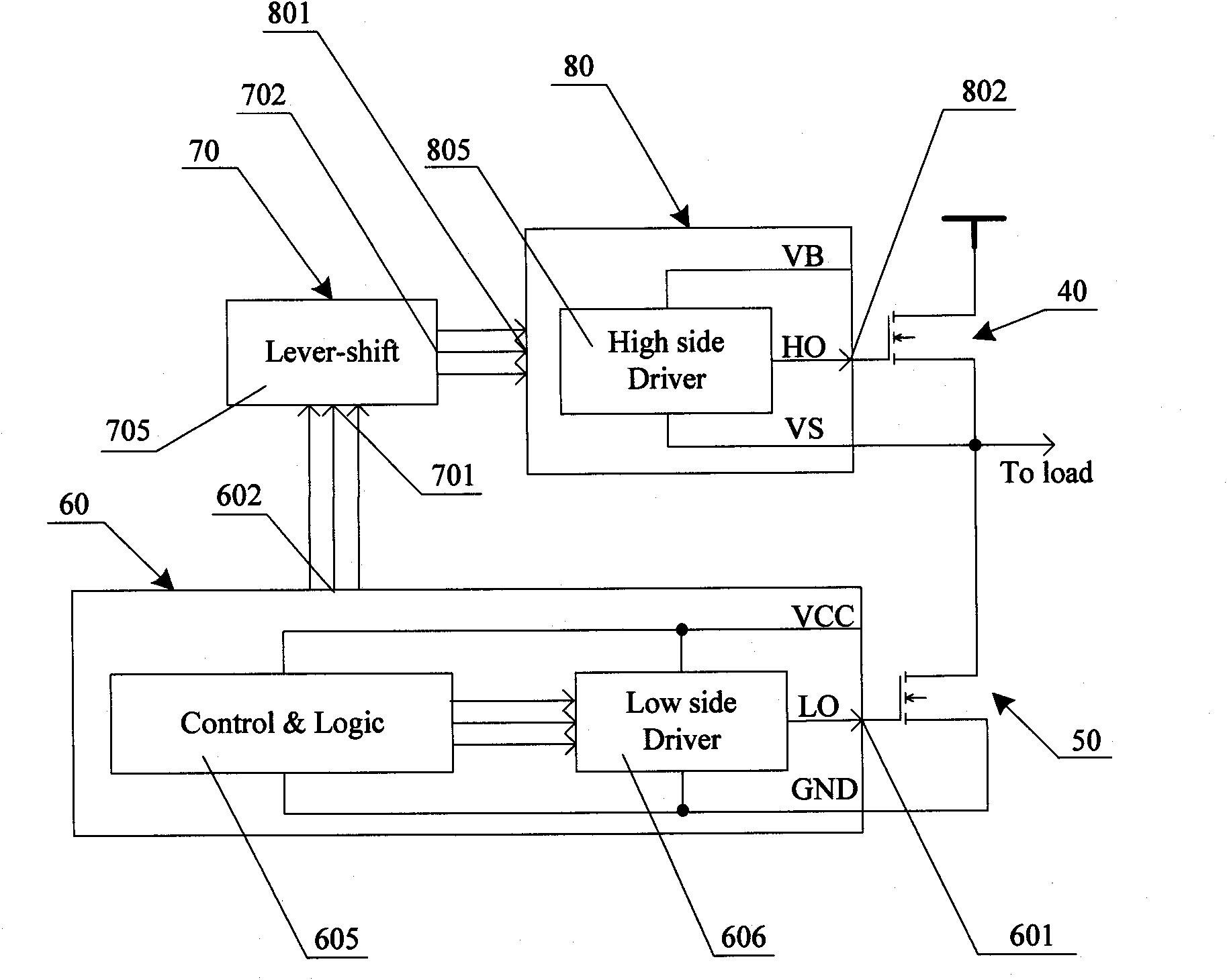
[0014] Such as figure 2 As shown, a gate drive circuit for controlling a bridge drive circuit includes a low-voltage side control chip 60 and a high-voltage side control chip 80 produced by a common CMOS process, and a level shifter chip 70 produced by a high-voltage isolation manufacturing process. The low-voltage side control chip 60 is mainly integrated by the control logic module 605 and the low-voltage side driver module 606, the first signal output port of the control logic module 605 is connected with the signal input port of the low-voltage side driver module 606, and the level shift chip 70 is mainly composed of The horizontal transfer module 705 is integrated, the high-voltage side control chip 80 is mainly integrated by the high-voltage side drive module 805, and the low-voltage side control chip 60 has a low-voltage side drive sig...


PUM


Abstract

The invention discloses a grid drive circuit for controlling a bridge type drive circuit. The grid drive circuit comprises a low-voltage side control chip, a high-voltage side control chip and a level shifting chip, wherein the low-voltage side control chip and the high-voltage side control chip are produced by adopting a complementary metal oxide semiconductor (CMOS) process; the level shifting chip is produced by a high-voltage isolation manufacturing process; the low-voltage side control chip is mainly integrated by a control logical module and a low-voltage side drive module; the level shifting chip is mainly integrated by a level shifting module; and the high-voltage side control chip is mainly integrated by a high-voltage side drive module. The grid drive circuit has the advantages that: singlechips for integrating all the modules are realized by being divided into three chips, the level shifting module is produced only by adopting the high-voltage isolation manufacturing process, and the control logical module, the low-voltage side drive module and the high-voltage side drive module are produced by adopting the CMOS process; and the grid drive circuit is encapsulated into an integrated circuit, so compared with the conventional grid drive chip, the complexity of the production process is reduced, the chip area is reduced, the production cost is reduced, and a circuit with more complicated properties can be designed favorably.

Description

technical field [0001] The present invention relates to a driving circuit, in particular to a gate driving circuit for controlling a bridge driving circuit. Background technique [0002] The bridge drive circuit is a common application circuit in the field of switching power supplies. The bridge drive circuit generally includes a half-bridge drive circuit and a full-bridge drive circuit. Two half-bridge drive circuits can be combined into a full-bridge drive circuit. The bridge drive circuit Circuits are often used in products such as electronic ballasts. figure 1 A schematic diagram of a typical half-bridge drive circuit in the prior art is given, the half-bridge drive circuit includes a first power device 10, a second power device 20 and a control chip, that is, a gate drive chip 30, the first power device 10 is used as a power device on the high-voltage side, and the second power device 20 is used as a power device on the low-voltage side. The gate driver chip 30 is refe...

Claims


Application Information

Patent Timeline
Patent Type & Authority Applications(China)
IPC IPC(8): H02M1/08
Inventor 姚海霆
Owner NINGBO SEMICON INT CORP
Why Eureka
Try Eureka