Eureka AIR delivers breakthrough ideas for toughest innovation challenges, trusted by R&D personnel around the world.

LED focusing optical system

An optical system and LED light source technology, applied in the field of optical systems, can solve problems such as high central light intensity and large luminous angle, and achieve the effects of simple structure, meeting lighting requirements, and large irradiation range

Inactive Publication Date: 2010-11-24
OCEANS KING LIGHTING SCI&TECH CO LTD +1
View PDF0 Cites 13 Cited by
  • Summary
  • Abstract
  • Description
  • Claims
  • Application Information

AI Technical Summary

Problems solved by technology

[0009] The technical problem to be solved by the present invention is to provide an LED concentrating optical system, which can improve the The central light intensity of spotlights with the same volume can ensure the light angle

Method used


Image

  • LED focusing optical system
  • LED focusing optical system
  • LED focusing optical system

Examples


Embodiment Construction

[0035] Such as Figure 4 as shown, Figure 4 It is a structural schematic diagram of the LED concentrating optical system of the first embodiment of the present invention. The LED concentrating optical system 3 of the present invention includes: an LED light source 31, a reflector 32 and a thin lens 33, the LED light source 31 is placed near the focus of the reflector 32, and the reflector 32 has an opening 321 at the other end of the LED light source 31, The thin lens 33 is placed at the opening 321 . In the first embodiment of the present invention, the reflector 32 is a parabolic reflector, the thin lens 33 is a plano-convex mirror, and the side of the plano-convex mirror facing the LED light source 31 is a plane 331, and the plane of the plano-convex mirror end and the opening end face of the reflector 32 are in contact with each other or there is a gap at intervals, the side of the plano-convex mirror facing away from the LED light source 31 is a convex surface 332, and...


PUM


Abstract

The invention relates to an LED focusing optical system which comprises a reflector, an LED light source arranged at the focal point of the bottom of the reflector and also a thin lens arranged at the opening of the reflector, wherein the surface of the thin lens opposite to the LED light source is a convex surface. The LED focusing optical system realizes high collection of light beams of the LED light source through combination of the thin lens and the reflector to enable the brightness of central light spots to be strong, the influence on an luminescence angle of the system by adding the thin lens is small i.e. the variation of light spots at the outer ring of a lamp is not large, the height of the optical system is only 2-4 times of the size of the light source, and the optical system has the advantages of simple structure, small volume, strong light intensity and large radiation range, therefore, the LED focusing optical system can be widely applied to the field of focusing lamps such as flashlights, miner lamps, headband lamps and the like and fully satisfy the illumination requirement of people to the focusing lamps.

Description

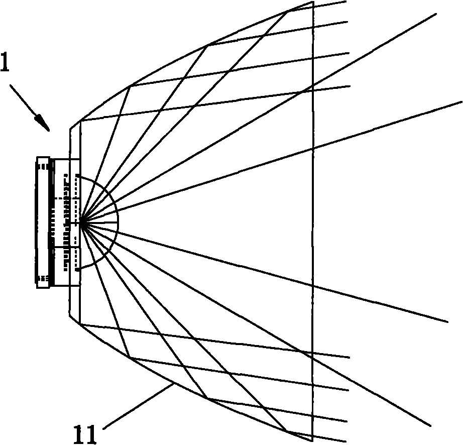
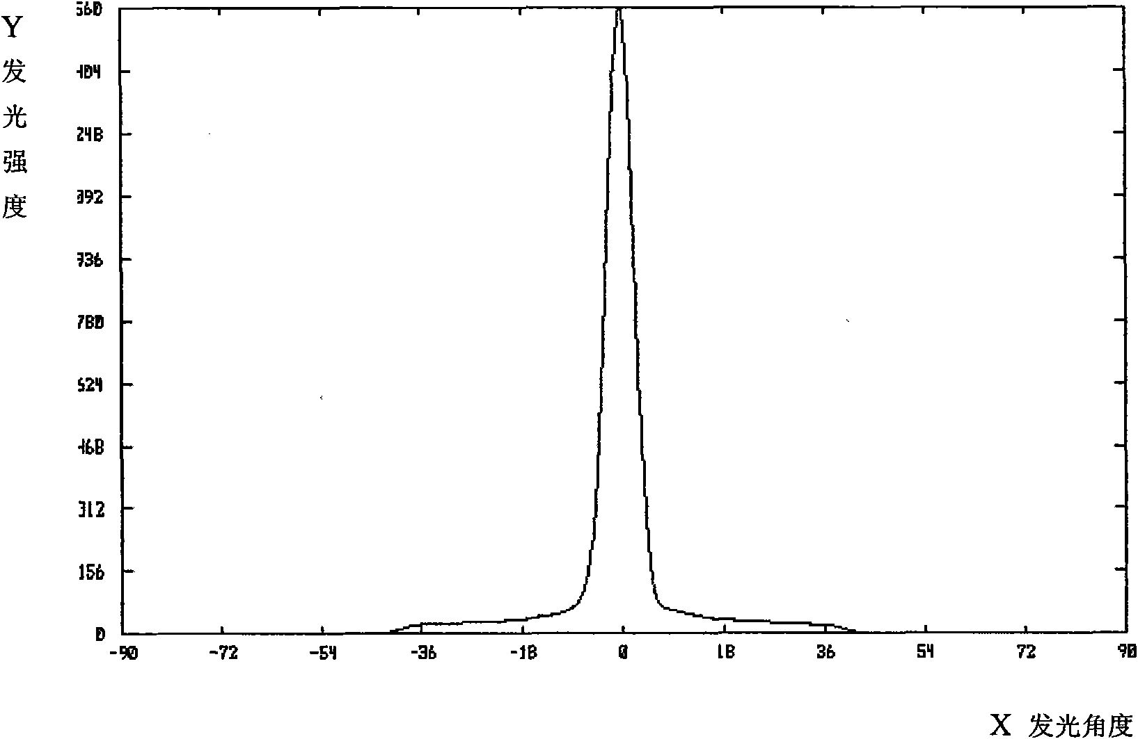
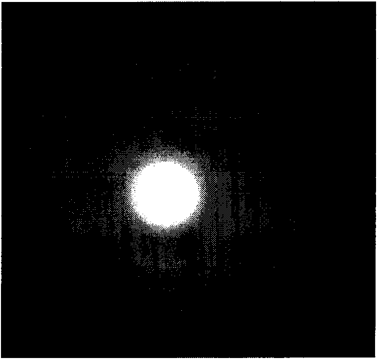
technical field [0001] The invention relates to the field of LED lighting lamps, and more specifically, relates to an optical system applied to LED spotlighting lamps. Background technique [0002] LED (Light Emitting Diode, that is, light-emitting diode) has the advantages of high light efficiency, good light quality, low energy consumption, long life, and small size. It has been widely used in the lighting industry, and it is more common in spotlights, such as flashlights. , miner's lamp, headband lamp, etc. At the same time, spotlights for work such as flashlights, miner's lamps, and headband lights are also popular with people for their lightness and compactness. [0003] At present, most LED spotlights adopt the light distribution method of parabolic reflector or condenser lens to achieve: [0004] Such as Figure 1A Shown in-C, adopt the optical system 1 of parabolic reflector 11 alone (referring to Figure 1A ), its light distribution curve (see Figure 1B ), the a...

Claims


Application Information

Patent Timeline
Patent Type & Authority Applications(China)
IPC IPC(8): F21V13/04H01L33/00F21Y101/02
Inventor 周明杰刘延明
Owner OCEANS KING LIGHTING SCI&TECH CO LTD
Why Eureka
Eureka Blog
Learn More