Radar antenna servo system design method based on structure and control integration

A servo system and radar antenna technology, applied in the field of antennas, can solve the problems of the variable structure of the radar antenna servo system, the stability, accuracy and rapidity of the dynamic target tracking control of the mechanism, and the incompatibility of the radar antenna servo system.

Inactive Publication Date: 2010-11-17
XIDIAN UNIV
View PDF4 Cites 4 Cited by
  • Summary
  • Abstract
  • Description
  • Claims
  • Application Information

AI Technical Summary

Problems solved by technology

[0011] (1) The nonlinear constraints such as the natural frequency of the mechanism, the stability, accuracy and rapidity of the dynamic target tracking control have not been considered, and the detailed integrated design that can simultaneously realize the light weight of the mechanism and the stable, accurate and fast tracking control has not been given Model
[0012] (2) It is only suitable for structural systems and simple mechanisms, and the approximate linearization method inevitably introduces model errors, which is not suitable for radar antenna servo systems
[0013] (3) For general servo systems, there are existing attempts to design structure and control integration, but because of the problems of variable structure and flexibility in radar antenna servo systems, these methods are not suitable for radar servo systems
[0014] To sum up, there is currently no comprehensive design method that considers both the structure and control performance of the radar antenna servo system to achieve its overall optimum

Method used


Image

  • Radar antenna servo system design method based on structure and control integration
  • Radar antenna servo system design method based on structure and control integration
  • Radar antenna servo system design method based on structure and control integration

Examples


Embodiment Construction

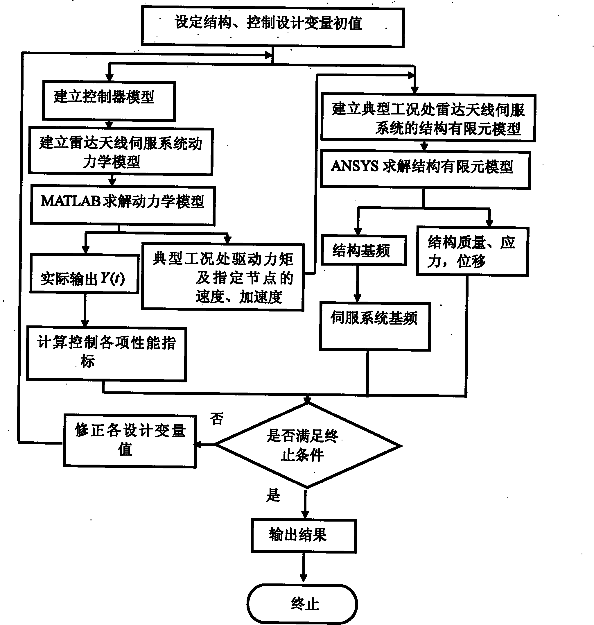
[0051] refer to figure 1 , the present invention includes as follows:

[0052] Step 1: Select an appropriate controller and set the initial value of the structure and control design variables.

[0053] (1.1) Select an appropriate controller for the specific control requirements of the radar antenna servo system;

[0054] (1.2) According to the reference input Y of the radar antenna servo system d (t), the lowest fundamental frequency f 1 , the maximum allowable stress Maximum allowable displacement Maximum control force or control torque τ max , the maximum overshoot ζ max and the maximum adjustment time Set the initial structural parameter d of the servo system, and the initial control gain coefficient p of the servo system;

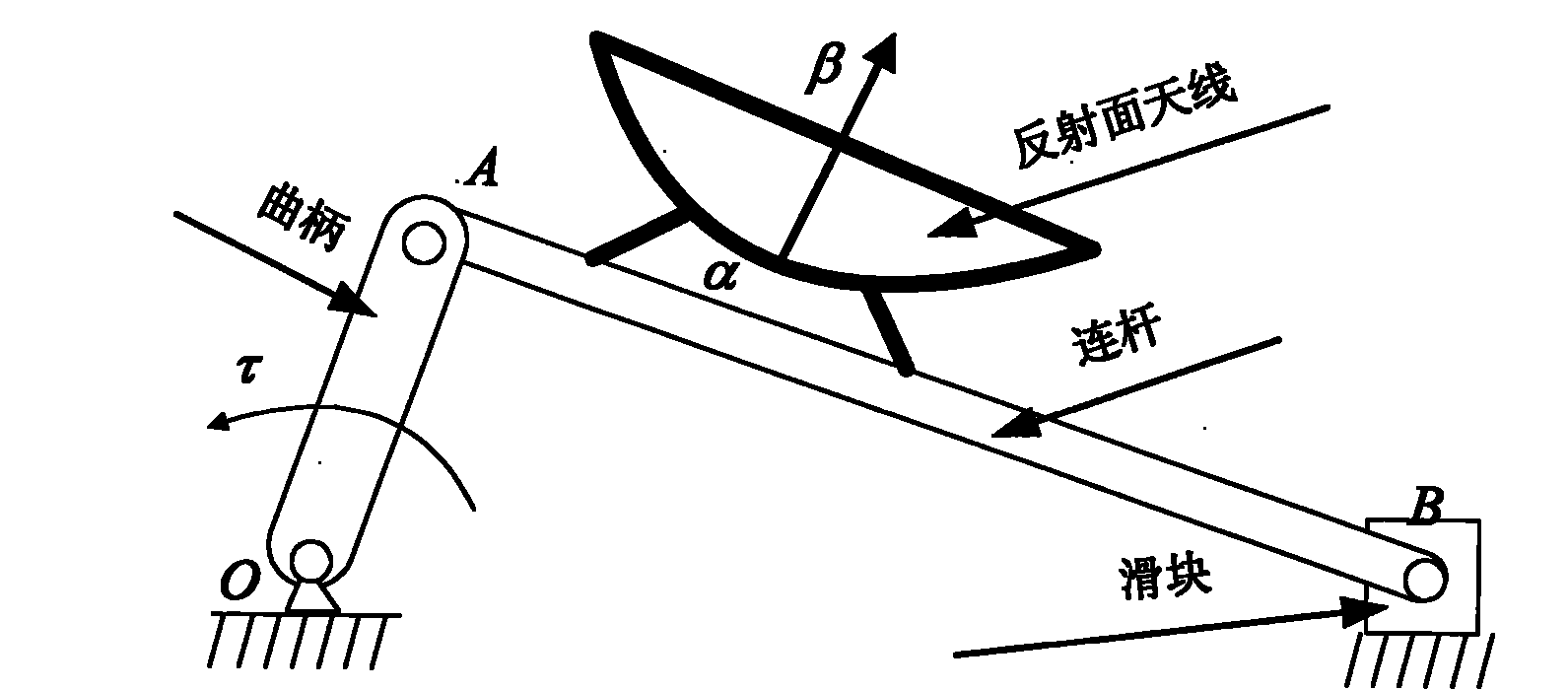
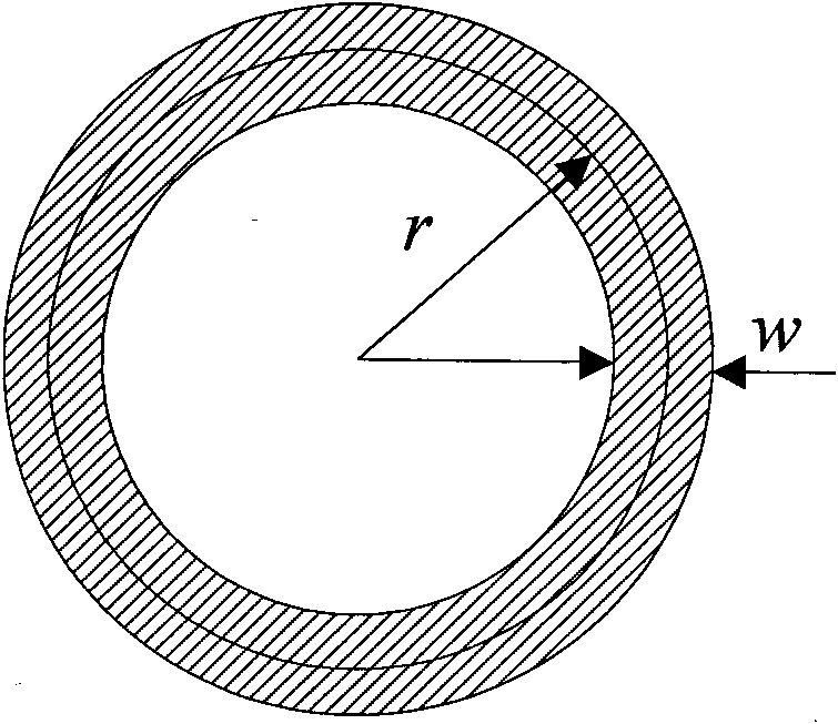
[0055] The initial structural parameter d is for the slider crank radar antenna servo system, including the median diameter r of the crank 1 , thickness w 1 , the pitch diameter r of the connecting rod 2 and thickness w 2 , but not limite...


PUM


Abstract

The invention discloses a radar antenna servo system design method based on structure and control integration, mainly solving the problem that the conventional sequent design method can not fully consider structure and control intercoupling. The design method comprises the following steps of: selecting an appropriate controller by taking a dynamical model of the radar antenna servo system as a basis, and solving a closed-loop response of the system; according to the control performance of a response computing system, the stress corresponding to the given working conditions and the motion situation of designated nodes on a member in the motion process of the servo system, establishing a structural dynamic differential equation of the radio antenna servo system under the working conditions, and carrying out structural finite element analysis to obtain structural characteristics of the servo system; and establishing an optimized mathematical model and solving a design variable which enables the whole performance of the servo system to be optimal aiming at structural performance requirements from a user on the tracking performance and the working conditions of the radar antenna servo system. The invention overcomes the defects in the traditional structure and control separation design method, not only can realize overall performance optimization, but also can remarkably shorten the preparation period.

Description

technical field [0001] The invention belongs to the technical field of antennas, in particular to a design method of a radar antenna servo system, which is used to guide the design of the radar antenna servo system. Background technique [0002] Radar is a device that uses the radio waves it emits to detect objects. The basic principle is this: the radar transmitter produces a strong radio wave, which is radiated into space through an antenna with excellent directivity. If this radio wave encounters a target, such as an aircraft, it will be reflected by the target. If it can Accept the reflected echo, and according to the characteristics of the echo, the position and other parameters of the target can be judged. In order to make the radiated radio waves irradiate the target and receive the echo of the target, it must automatically track the target after searching for the target. The search target and automatic tracking target are realized by means of the radar antenna serv...

Claims


Application Information

Patent Timeline
Patent Type & Authority Applications(China)
IPC IPC(8): G05B17/00
Inventor 段宝岩李素兰黄进张逸群
Owner XIDIAN UNIV
Why Eureka
Try Eureka