
Front focusing and focus-fixing projection lens

A projection lens and focusing technology, which is applied in the field of front-group focusing and fixed-focus projection lenses, can solve the problems of large volume and inconvenience to carry, and achieve the effect of clear projection image, compact structure, and ensuring the utilization rate of light energy.

Active Publication Date: 2012-07-25
NANYANG LIDA PHOTOELECTRIC
View PDF0 Cites 0 Cited by
  • Summary
  • Abstract
  • Description
  • Claims
  • Application Information

AI Technical Summary

Problems solved by technology

In the past, most of the light sources used in DLP projectors were UHP (Ultra High Pressure Mercury Lamps), which were bulky and not easy to carry.

Method used


Image

  • Front focusing and focus-fixing projection lens
  • Front focusing and focus-fixing projection lens
  • Front focusing and focus-fixing projection lens

Examples


Embodiment Construction

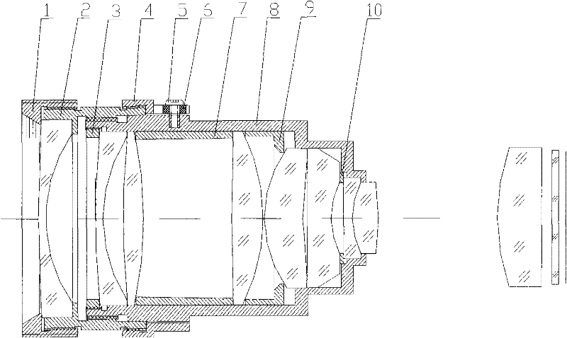
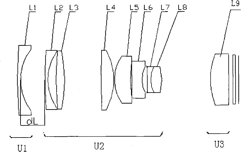
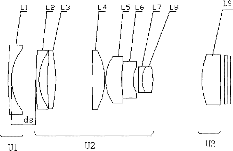
[0030] combine figure 1 , see figure 2 , image 3 , the front group of the present invention focus fixed focus projection lens, the main components include focus pressure ring 1, focus lens barrel 2, pressure ring 3, focus limit ring 4, focus limit screw 5, focus limit sleeve Barrel 6, spacer ring 7, main lens barrel 8, spacer ring 9, spacer ring 10 and optical system lens group, the optical system lens group consists of a focusing group U1 with negative refractive power and a fixed group U2 with positive refractive power and positive light The focus group U1, the fixed group U2 and the field lens U3 are arranged in sequence from the screen side to the image plane side along the optical axis. Among them: the focusing lens barrel 2 is connected with the main lens barrel 8 through a multi-thread thread, and the front part is equipped with a focusing pressure ring 1, and the turning of the focusing pressure ring 1 can drive the focusing lens barrel 2 to rotate accordingly to r...


PUM


Abstract

The invention relates to a front focusing and focus-fixing projection lens, which is mainly used for a DMD digital micro-mirror array reflection projection system (DLP). The front focusing and focus-fixing projection lens is mainly characterized in that: an optical system in the lens consists of a focusing group [U1] with negative optical power, a fixing group [U2] with positive optical power anda field lens [U3] with positive optical power, wherein the [U1], [U2] and [U3] are sequentially arranged from a screen side to an image plane side along an optical axis. Due to forward and backward movement of the [U1] group, the imaging requirement on different projection distances is met. The system has the characteristics of front focusing, simple structure, small caliber of a tail section of the lens, long rear operating distance, and the like. The lenses in the lens are all spherical lenses, and have the advantages of good manufacturability and suitability for mass production.

Description

technical field [0001] The invention belongs to the technical field of optical appliances, and relates to a front group focus-adjusting and fixed-focus projection lens suitable for use with a non-telecentric illumination light path on a DLP projector. Background technique [0002] DLP projection display technology has developed rapidly in recent years, and its core components mainly use the DMD digital image chip exclusively mastered and developed by Texas Instruments. There are two main types of DLP projection lighting optical path systems: total reflection prism (TIR prism) telecentric optical path system and catadioptric non-telecentric optical path system. There are also two types of projection display lenses that match the illumination light path: image-side telecentric imaging systems and non-telecentric imaging systems. This projection lens belongs to the latter. [0003] In recent years, high-power LED light-emitting chip technology has achieved rapid development. ...

Claims


Application Information

Patent Timeline
Patent Type & Authority Patents(China)
IPC IPC(8): G02B15/177G03B21/00
Inventor 曹红曲李跃甫赵武
Owner NANYANG LIDA PHOTOELECTRIC
Learn More