Method for manufacturing light guide plate

A manufacturing method and technology for a light guide plate, which are applied to optical components, applications, household appliances, etc., can solve the problems of poor consistency and reproducibility, increased cost, high cost, etc., and achieve a convenient and simple manufacturing process and improve production efficiency. , the effect of increasing productivity

Inactive Publication Date: 2012-10-24
ATC OPTOELECTRONICS DONGGUAN
View PDF1 Cites 0 Cited by
  • Summary
  • Abstract
  • Description
  • Claims
  • Application Information

AI Technical Summary

Problems solved by technology

[0007] From the measured data in Table 1, it can be seen that the brightness and uniformity of the light guide plate produced by these two dot processing methods are not very ideal.
Moreover, compared with high-efficiency ultra-bright and ultra-thin light guide plates, the corrosion method is very sensitive to temperature and humidity, and the consistency and reproducibility are poor.
The laser method is prone to craters around the dots, resulting in poor directivity of the light and poor stability of injection molding
The cutting process is expensive, and it is often used in notebook computers at present, and the process is very complicated, which requires extremely high production environment and equipment capabilities, resulting in increased costs.

Method used


Image

  • Method for manufacturing light guide plate
  • Method for manufacturing light guide plate
  • Method for manufacturing light guide plate

Examples


Embodiment Construction

[0022] In order to further understand the features, technical means, and specific objectives and functions achieved by the present invention, the present invention will be further described in detail below in conjunction with the accompanying drawings and specific embodiments.

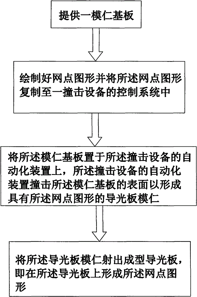
[0023] see figure 1 , is a flowchart of the manufacturing method of the light guide plate of the present invention. The manufacturing method of the light guide plate of the present invention comprises the following steps:

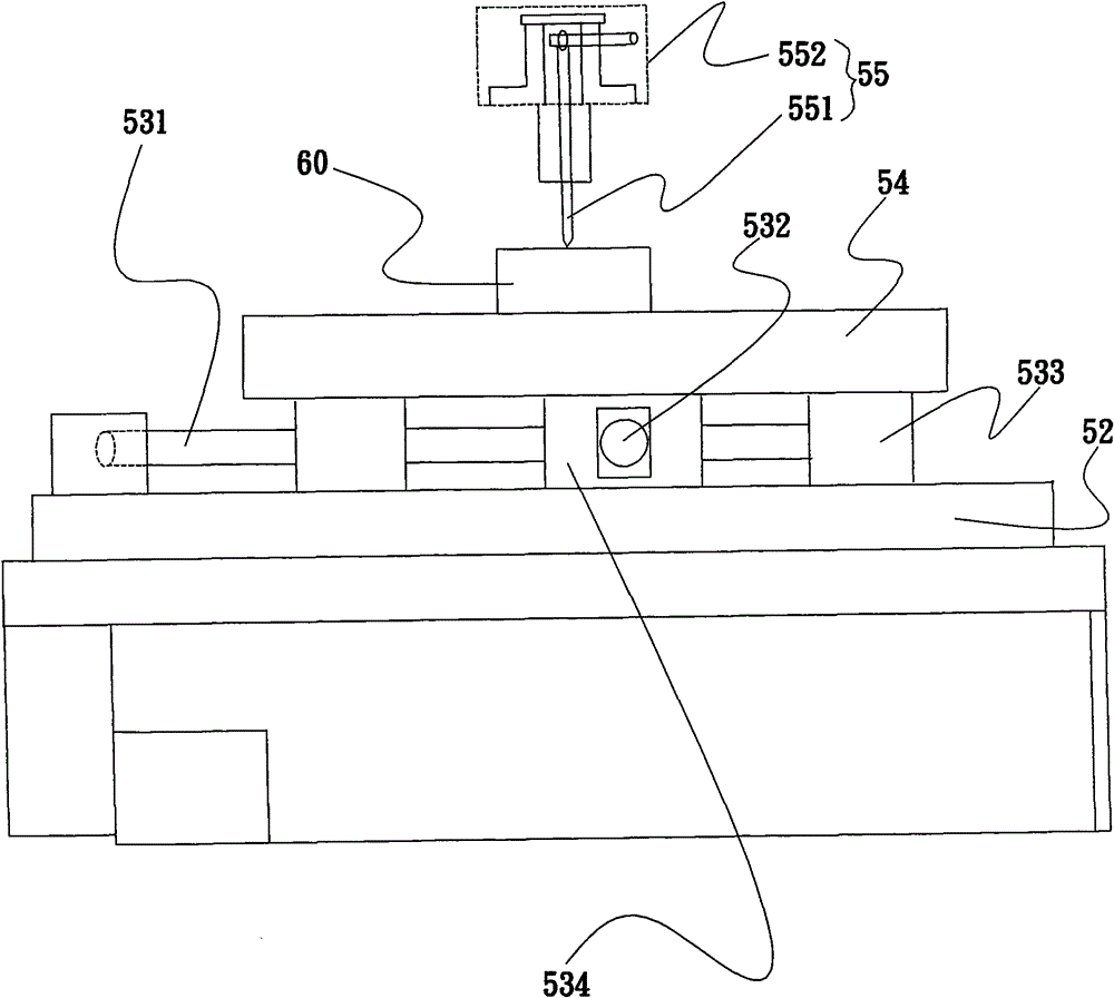
[0024] Step ①, providing a core substrate 60 .

[0025] In step ②, draw the dot pattern and copy the dot pattern to the control system of an impact device.

[0026] In step ③, the mold core substrate 60 is placed on the automation device of the impact equipment, and the automation device of the impact equipment impacts the surface of the mold core substrate 60 to form a light guide plate mold core with the dot pattern ( not shown in the figure).

[0027] In step ④, inject the co...


PUM

PropertyMeasurementUnit
depthaaaaaaaaaa
diameteraaaaaaaaaa
thicknessaaaaaaaaaa

Abstract

The invention discloses a method for manufacturing a light guide plate, which comprises the following steps of: (1) providing a mold core substrate; (2) drawing a dot pattern, and copying the dot pattern into a control system of an impact facility; (3) putting the mold core substrate on an automatic device of the impact facility, wherein the automatic device of the impact facility impacts the surface of the mold core substrate to form the light guide plate mold core with the dot pattern; and (4) injection-molding the light guide plate by using the light guide plate mold core, which means to form the dot pattern on the light guide plate. In the method, the automatic device of the impact facility is utilized to impact the surface of the mold core substrate to form the light guide plate moldcore with the dot pattern, and the light guide plate is injection-molded by using the light guide plate mold core. Thus, the invention has the advantages of convenient and simple manufacturing process and lower cost, and is beneficial to enhancing the production efficiency and the production capacity.

Description

technical field [0001] The invention relates to a method for manufacturing a light guide plate, in particular to a method for manufacturing a light guide plate with a simple manufacturing process, which is convenient for mass production and saves costs. Background technique [0002] In today's technology, the light guide plate is the heart of the LED backlight module. The function of the light guide plate is to guide the scattering direction of light, thereby improving the brightness of the liquid crystal display and ensuring the uniformity of the brightness of the liquid crystal display. LED backlight module has a great influence. Therefore, the design and manufacture of the light guide plate in the edge-lit LED backlight module is one of the key technologies. There are many diffusion points on the light guide plate. The light source is located on the side of the light guide plate. The light emitted by the light source is transmitted to the other end by reflection. When th...

Claims


Application Information

Patent Timeline
Patent Type & Authority Patents(China)
IPC IPC(8): B29C45/00B29C45/17B29K69/00B29K33/04B29L11/00
Inventor 薛峰
Owner ATC OPTOELECTRONICS DONGGUAN
Why Eureka
Try Eureka