
System for supplying heat and heating condensate water by extracting residual heat of power plant through heat pump

A technology for waste heat and condensed water in power plants, applied in heating systems, hot water central heating systems, energy-saving heating/cooling, etc., can solve problems such as large power consumption, energy waste, and urban thermal pollution, and achieve the effect of reducing evaporation

Inactive Publication Date: 2010-11-10
SHENYANG HUAYU GROUND SOURCE HEAT PUMP HEATING
View PDF0 Cites 9 Cited by
  • Summary
  • Abstract
  • Description
  • Claims
  • Application Information

AI Technical Summary

Problems solved by technology

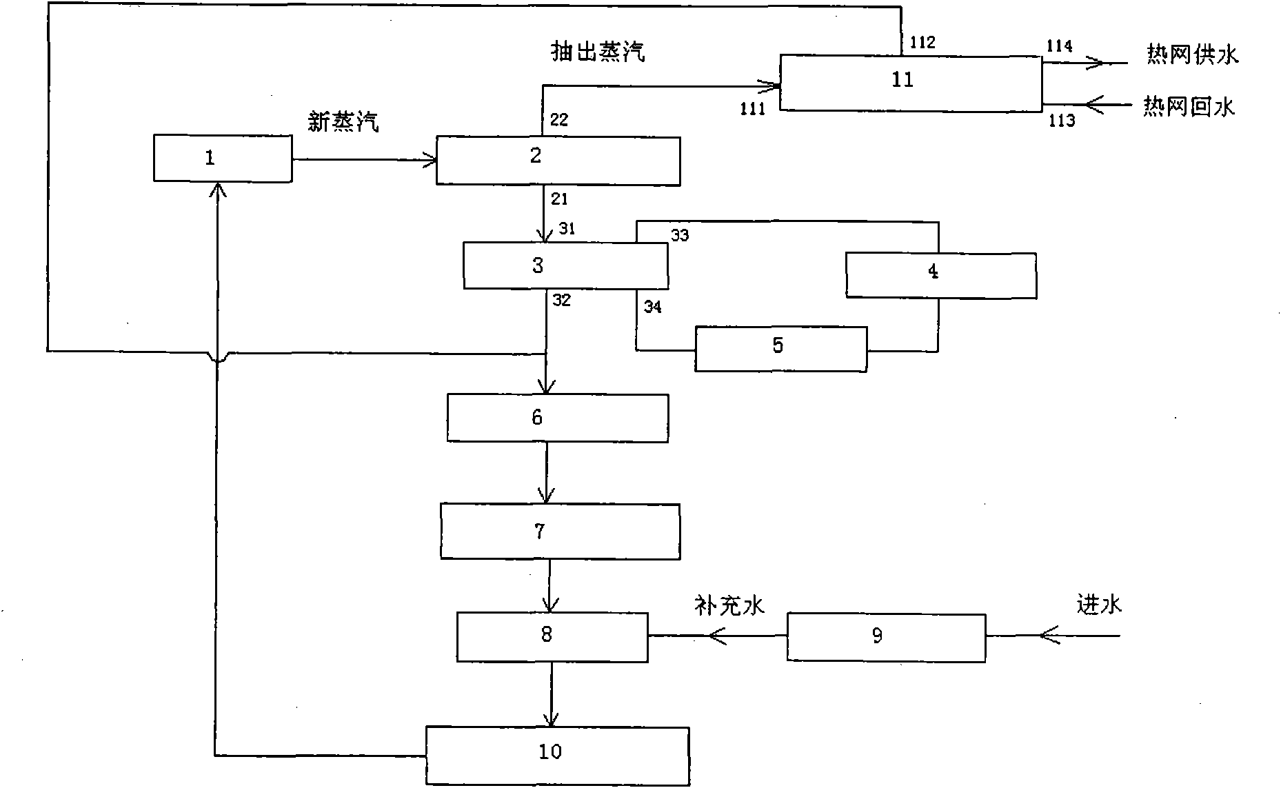
In this way, not only a large amount of heat energy is discharged into the atmosphere, resulting in a great waste of energy and heat pollution to the air, but also because the cooling circulating water will evaporate in large quantities when passing through the cooling water tower, resulting in a large waste of water resources. Water pumps and cooling tower fans also consume a lot of electricity
[0006] Especially in summer, the temperature of the cooling circulating water after passing through the condenser can reach 40-50°C. It is not only a pity that the heat is released into the atmosphere, but also causes a large amount of water consumption due to the evaporation of water, and it is harmful to the city. cause serious heat pollution

Method used


Image

  • System for supplying heat and heating condensate water by extracting residual heat of power plant through heat pump
  • System for supplying heat and heating condensate water by extracting residual heat of power plant through heat pump
  • System for supplying heat and heating condensate water by extracting residual heat of power plant through heat pump

Examples


Embodiment Construction

[0013] The drawings and embodiments of the system structure for extracting waste heat from a power plant for heating and heating condensed water provided by the present invention are described in detail as follows:

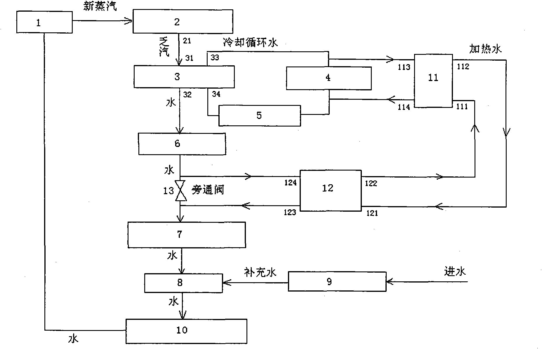
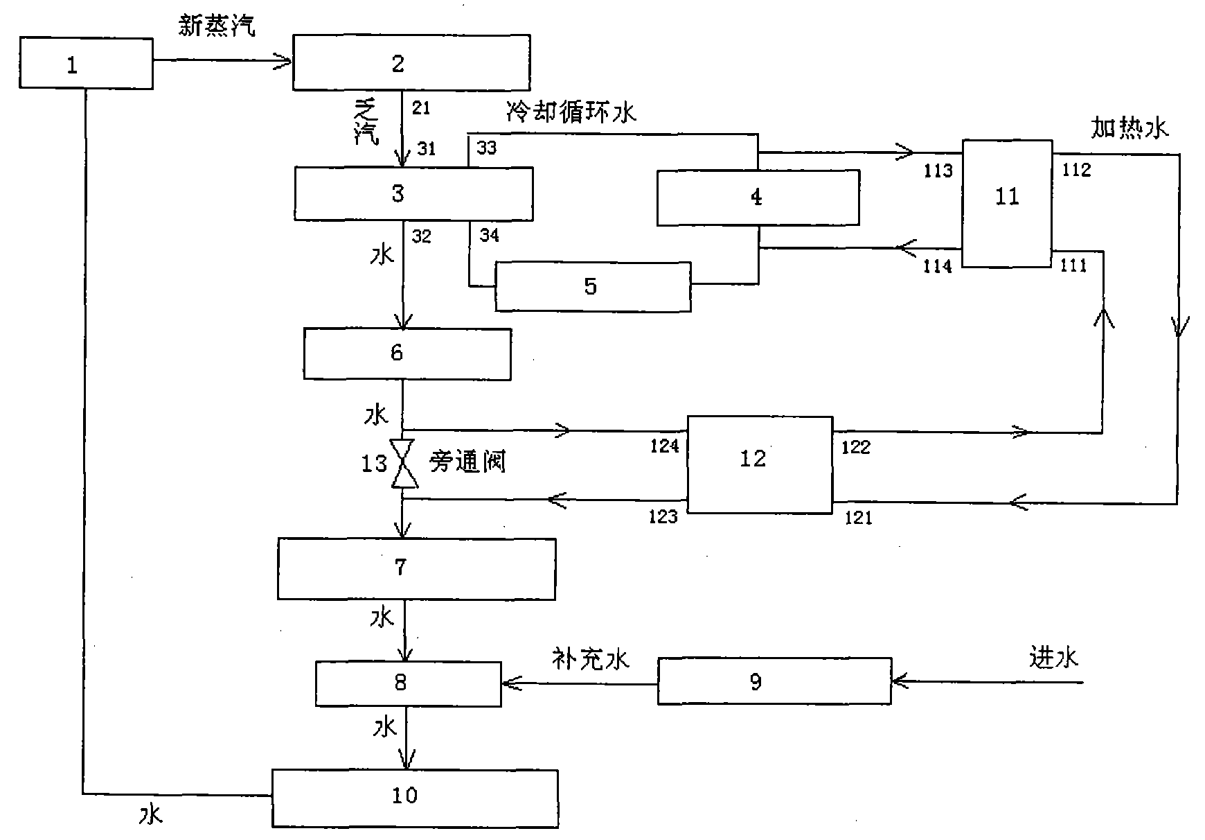
[0014] The structure of the present invention is as figure 2 As shown, the system mainly includes: boiler 1, steam turbine 2, condenser 3, cooling water tower 4, circulating water pump 5, condensate pump 6, low pressure regenerative heater 7, deaerator 8, chemical water processor 9, high pressure The regenerative heater 10, the heat pump unit 11, the heat exchanger 12 and the bypass valve 13 are connected as follows: the outlet of the boiler 1 is connected with the inlet of the steam turbine 2, and the outlet of the steam turbine 2 is connected with the heat inlet 31 of the condenser 3 , The hot outlet 32 ​​of the condenser 3 is connected to the inlet of the condensate pump 6, the cold outlet 33 of the condenser 3 is connected to the inlet of the cooling tower 4 and...


PUM


Abstract

The invention relates to a system for supplying heat and heating condensate water by extracting residual heat of a power plant through a heat pump, belonging to the technical field of thermoelectricity. The system mainly comprises a boiler, a steam turbine, a condenser, a condensate water pump, a low-pressure bleeder heater, a deaerator, a high-pressure bleeder heater, a water-cooling tower, a water-circulating pump, a chemical water treater, a heat pump unit, a heat exchanger and a by-pass valve, wherein the boiler is sequentially connected with the steam turbine, the condenser, the condensate water pump, the low-pressure bleeder heater, the deaerator and the high-pressure bleeder heater into a loop; the condenser, the water-cooling tower and the water-circulating pump are connected into the loop; the heat outlet of the heat pump unit is respectively connected with the heat inlet of the heat exchanger and the water supply of a heat network; and the heat inlet of the heat pump unit is respectively connected with the heat outlet of the heat exchanger and the return water of the heat network. The invention can recover the heat energy in the cooling water of the power plant, reduces the evaporation capacity of the cooling circulating water, and saves energy and water.

Description

Technical field [0001] The invention belongs to the field of thermoelectric technology. Background technique [0002] In thermal power plants, the steam drives the steam turbine to generate electricity. The steam that drives the steam turbine to generate electricity becomes exhausted steam that can no longer perform work after being generated by the steam turbine. When it passes through the condenser, it is cooled by the circulating cooling water to liquid water and then returned to the boiler for circulating cooling. The water takes away the heat in the exhaust steam and discharges it into the atmosphere through the cooling water tower. [0003] Existing power plant systems such as figure 1 As shown, the system includes a boiler 1, a steam turbine 2, a condenser 3, a condensate pump 6, a low-pressure regenerative heater 7, a deaerator 8, and a high-pressure regenerative heater 10 connected by pipelines. [0004] The working principle of the system is: the steam produced by boiler 1...

Claims


Application Information

Patent Timeline
Patent Type & Authority Applications(China)
IPC IPC(8): F01K11/02F01K17/02F24D3/18
CPCY02B30/12Y02B30/16
Inventor 张军
Owner SHENYANG HUAYU GROUND SOURCE HEAT PUMP HEATING
Learn More