Two-crawler material paving machine
A paver and crawler technology, applied in the field of two crawler type material paver, can solve the problems of inconvenient transition, limitation, and inability of the paver to drive directly, so as to reduce the engineering cost and reduce the passing width.
- Summary
- Abstract
- Description
- Claims
- Application Information
AI Technical Summary
Problems solved by technology
Method used
Image
Examples
Embodiment 1
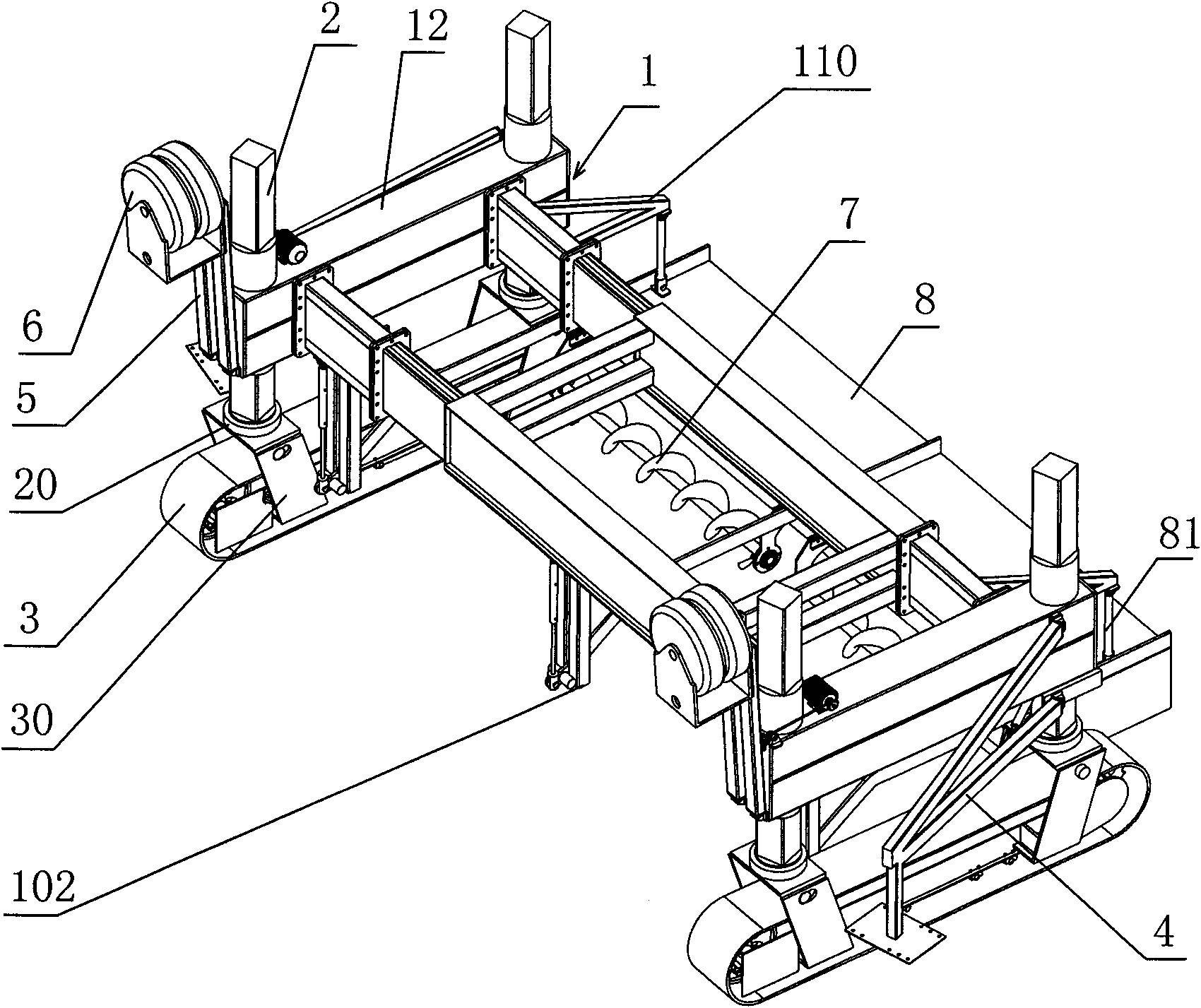
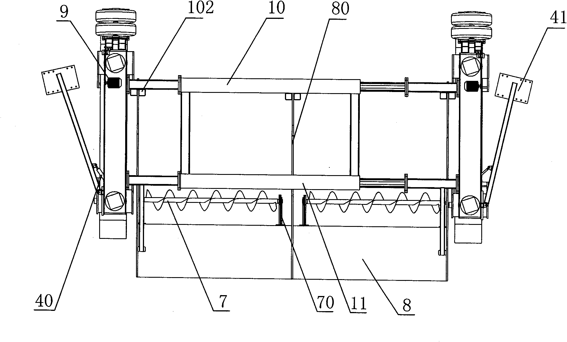
[0062] Such as figure 1 with figure 2 As shown, the main frame 1 of the two-track material paver that can transfer on its own in this embodiment mainly includes a front beam 10, a rear beam 11, and connecting front beams 10 and rear beams installed at the left and right ends of the front beam 10 and the rear beam 11. Side beams 12 of cross beams 11 . For ease of description, the direction parallel to the front beam 10 of the main frame is defined as the transverse direction, and the advancing direction of the paver is defined as the front. The front beam 10 includes a sliding sleeve type telescopic part (unlabeled) and a laterally extended flange section (unlabeled) controlled by a hydraulic cylinder, and the rear beam 11 also includes a sliding sleeve type telescopic section controlled by a hydraulic cylinder and a laterally extended flange section . The sliding sleeve type expansion part is a conventional design in mechanical design, mainly including relatively movable i...
Embodiment 2
[0071] Such as Figure 4 As shown, the difference between this embodiment and Embodiment 1 is that the pivot of the support pendulum 4 is installed on the outer wall of the front part of the side beam 12, and one end of the steering control cylinder 40 is installed on the lower part and the other end of the support pendulum 4. Installed on the bottom wall of the side beam 12 front. The rear portion of the running gear mounting frame 5 is hinged on the outer side wall of the side beam 12 rear portion, and the rear portion of the running gear mounting frame 5 is equipped with a connecting rod 50 ( Figure 5 ), the connecting rod 50 is hinged with the lifting cylinder 51 installed on the side beam 12, and is used to lift or put down the running gear installation frame 5. The walking crawler 3 is provided with three installation parts 30, which are located at both ends and the middle of the walking crawler 3 respectively.
[0072] Such as Figure 5 and Image 6 As shown, durin...
Embodiment 3
[0074] Such as Figure 7 As shown, the difference between this embodiment and Embodiment 1 is that the mounting seat 20 is directly installed on the bottoms of the front and rear ends of the side beam 12, and the mounting parts 30 at both ends of the walking track 3 are mounted on the mounting seat 20 through pin shafts. The running gear mounting frame 5 is hinged on the front side wall of the side beam 12, and a mutually hinged connecting rod 50 and a lifting cylinder 51 are installed between the lateral wall of the side beam 12 front end and the running gear mounting frame 5 . The central rotating shaft 4' passing through the side beam 12 vertically is installed on the mounting seat 20 located at the back, and the upper and lower ends of the central rotating shaft 4' are equipped with a disc 41' as a support arm mounting part, and the disc 41' The outer diameter is greater than the width of the side beam 12—that is, the disc 41' protrudes from both sides of the side beam 12,...
PUM
 Abstract
Description
Claims
Application Information
 - R&D Engineer
- R&D Manager
- IP Professional
- Industry Leading Data Capabilities
- Powerful AI technology
- Patent DNA Extraction
Browse by: Latest US Patents, China's latest patents, Technical Efficacy Thesaurus, Application Domain, Technology Topic, Popular Technical Reports.
© 2024 PatSnap. All rights reserved.Legal|Privacy policy|Modern Slavery Act Transparency Statement|Sitemap|About US| Contact US: help@patsnap.com


