
Method and device for producing synthetic natural gas

A technology for synthesizing natural gas and product gas, which is applied in the production of synthetic natural gas and complete methanation. It can solve the problems of high energy consumption, high operating cost, and low methane concentration, and achieve reasonable process flow, operability, and material requirements. low effect

Active Publication Date: 2010-11-10
DATANG INT CHEM TECH RESINST +1
View PDF4 Cites 29 Cited by
  • Summary
  • Abstract
  • Description
  • Claims
  • Application Information

AI Technical Summary

Problems solved by technology

[0003] The main problems of coal hydrogasification to produce methane are: low carbon conversion rate, low methane yield, complex gas composition, low methane concentration, and lack of high-quality synthetic natural gas, etc.
[0004] The Lurgi, HICOM and TREMP methanation processes all adopt part of the high-temperature and high-water process gas circulation method to reduce the operating temperature of the first-stage reactor, reduce the risk of carbon precipitation in the catalyst bed, and improve the heat utilization efficiency of the methanation reaction. Expensive circulating compressors are required, and the requirements for reactors, waste pots and steam superheaters are high, and the device has disadvantages such as high operating energy consumption and high operating costs, and even if some high-temperature and high-water process gas circulation methods are adopted, high-temperature The risk of carbon precipitation in the catalyst bed is also very high
[0005] The methanation reaction is a fast and strongly exothermic reaction. If the carbon monoxide content in the feed gas is too high, it will cause a large amount of heat release, which will easily cause the catalyst bed to overheat and carbon precipitation, resulting in catalyst deactivation and even endangering the safety of the reactor.

Method used


Image

  • Method and device for producing synthetic natural gas
  • Method and device for producing synthetic natural gas
  • Method and device for producing synthetic natural gas

Examples


Embodiment approach 1

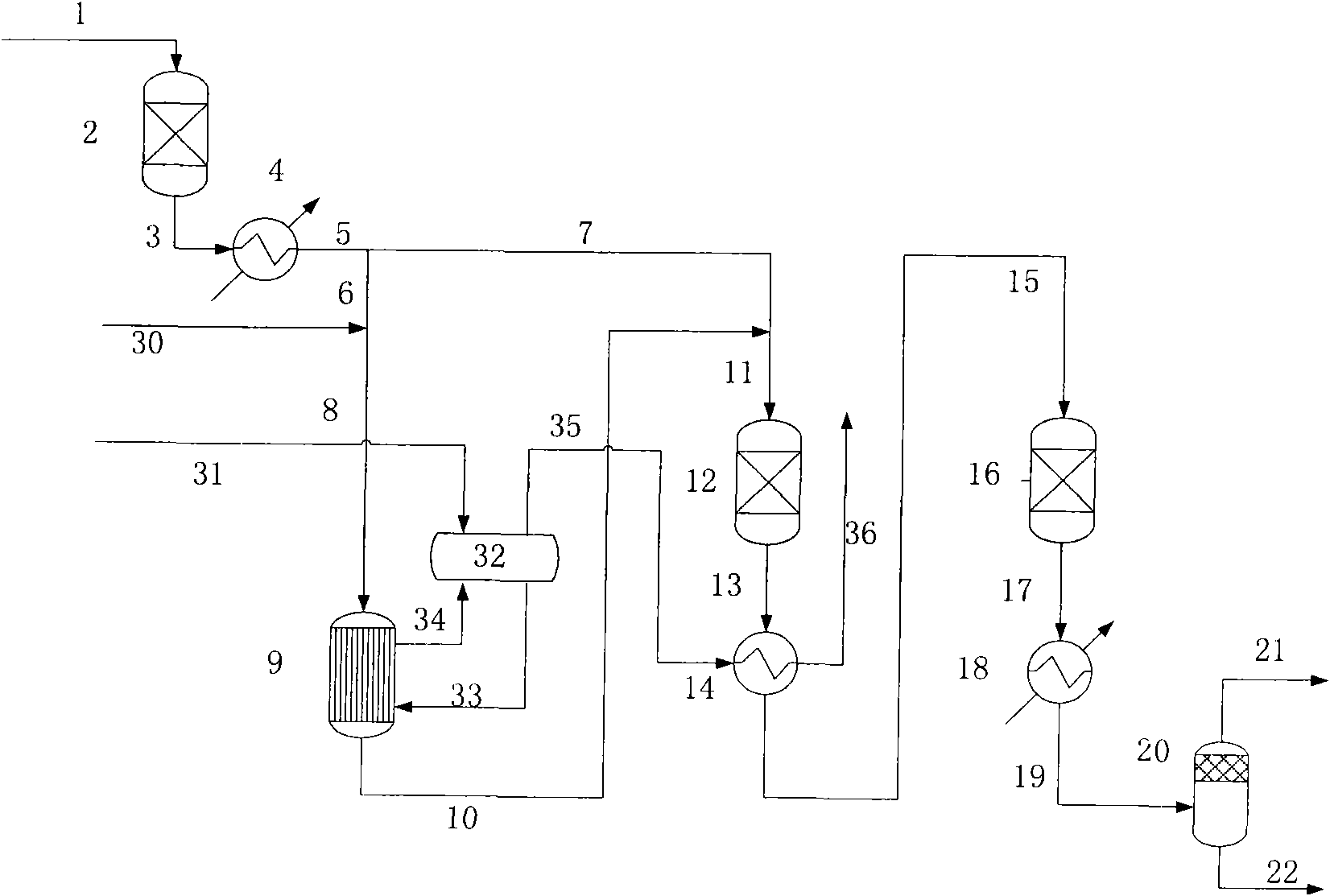
[0053] figure 1 Shown is a preferred embodiment of the production method of synthetic natural gas provided by the present invention.

[0054] The main raw material synthesis gas is produced by the gasifier, and through conventional steps such as quenching, impurities such as tar, phenol, ammonia and dust are removed, and the sulfide and some carbon dioxide contained in it are removed by the acid gas removal unit. The raw material gas 1 passing through the acid gas removal unit enters the purification reactor 2 to further remove trace impurities such as sulfur and oxygen contained therein. The purified raw material gas 3 is preheated by the heat exchanger 4 and divided into two streams, that is, the first raw material gas 6 and the second raw material gas 7 . The first raw material gas 6 is mixed with steam 30, and the temperature of the obtained mixed gas 8 is 250-350°C, which is passed into the first-stage cooling type tubular reactor 9 filled with a methanation catalyst to ...

Embodiment approach 2

[0059] figure 2 Shown is another preferred implementation of the method for producing synthetic natural gas provided by the present invention.

[0060] The main raw material synthesis gas is produced by the gasifier, and through conventional steps such as quenching, impurities such as tar, phenol, ammonia and dust are removed, and the sulfide and some carbon dioxide contained in it are removed by the acid gas removal unit. The raw material gas 1 passing through the acid gas removal unit enters the purification reactor 2 to further remove trace impurities such as sulfur and oxygen contained therein. The purified raw material gas 3 is preheated by the heat exchanger 4 and divided into two streams, that is, the first raw material gas 6 and the second raw material gas 7 . The first raw material gas 6 is mixed with steam 30, and the temperature of the obtained mixed gas 8 is 250-350°C, which is passed into the first-stage cooling type tubular reactor 9 filled with a methanation c...

Embodiment approach 3

[0064] For comparison with Embodiment 1 and Embodiment 2, under the same basic design conditions, the traditional methanation process is used to produce synthetic natural gas. The specific process flow chart is as image 3 shown.

[0065]The main raw material synthesis gas is produced by the gasifier, and through conventional steps such as quenching, impurities such as tar, phenol, ammonia and dust are removed, and the sulfide and some carbon dioxide contained in it are removed by the acid gas removal unit. The raw material gas 1 passing through the acid gas removal unit enters the purification reactor 2 to further remove trace impurities such as sulfur and oxygen contained therein. The purified raw material gas 3 is preheated by the heat exchanger 4 and divided into two streams, that is, the first raw material gas 6 and the second raw material gas 7 . The first raw material gas 6 is mixed with the recycle gas 27', and the temperature of the obtained mixed gas 8' is 250-350°...


PUM


Abstract

The invention provides a new method and a device for producing synthetic natural gas. The method comprises continuous process flows of producing methane-rich gas containing over 94 mole percent of methane by using a coal gasification product as a raw material. The method provided by the invention does not use an expensive circulation compressor, reduces the operation cost and reduces the materialrequirements of a reactor, a waste boiler and a steam over-heater. The method has low requirement for catalyst operating temperature; a catalyst bed layer is not easy to cause temperature runaway andcan inhibit carbon precipitation so as to remarkably reduce the energy consumption of a methanation process; and the method has the advantages of reasonable process flows, operability, energy conservation and the like.

Description

technical field [0001] The invention relates to a method for complete methanation. Specifically, the invention relates to a method and a device for producing synthetic natural gas by using coal gasification products as raw materials, and belongs to the technical field of synthetic natural gas. Background technique [0002] Since the 1970s, along with the oil crisis, coal-to-methane (synthetic natural gas or alternative natural gas) has developed rapidly. The main methods of coal-to-methane include direct production of methane by coal hydrogasification and indirect production of methane through synthesis gas. [0003] The main problems of coal hydrogasification to produce methane are: low carbon conversion rate, low methane yield, complex gas composition, low methane concentration, and lack of high-quality synthetic natural gas. Relatively speaking, the process of producing methane from coal through syngas has significant advantages of high technological maturity, high carbo...

Claims


Application Information

Patent Timeline
IPC IPC(8): C10L3/08F22B1/18F22G1/14
Inventor 李春启左玉帮刘永健邱波忻仕河
Owner DATANG INT CHEM TECH RESINST
Learn More