


Quick Research
Generate reliable direction feasibility study reports for your R&D in just a few steps.

Technical Q&A
Discover and master advanced knowledge NOW. Basics, ideas, possibilities, all at once.

Find Solutions
As an expert in R&D theories, this can generate solutions to your technical problems instantly.

Evaluate Feasibility
Analyze your overall solution with one click, know your potential R&D risks in advance.

Monitor Landscape
Get weekly tech updates, stay abreast of the latest tech innovations and key insights.
Dipping type film-separating apparatus, and film cartridge
A separation device and submerged membrane technology, applied in the direction of semi-permeable membrane separation, membrane, membrane technology, etc., can solve problems such as the failure of suction pressure to achieve increased safety, reduce dangerous operations at high places, and reduce labor volume effect
- Summary
- Abstract
- Description
- Claims
- Application Information
AI Technical Summary
Problems solved by technology
Method used
Image


Examples
Embodiment Construction
[0096] Next, a first embodiment of the present invention will be described with reference to the drawings.
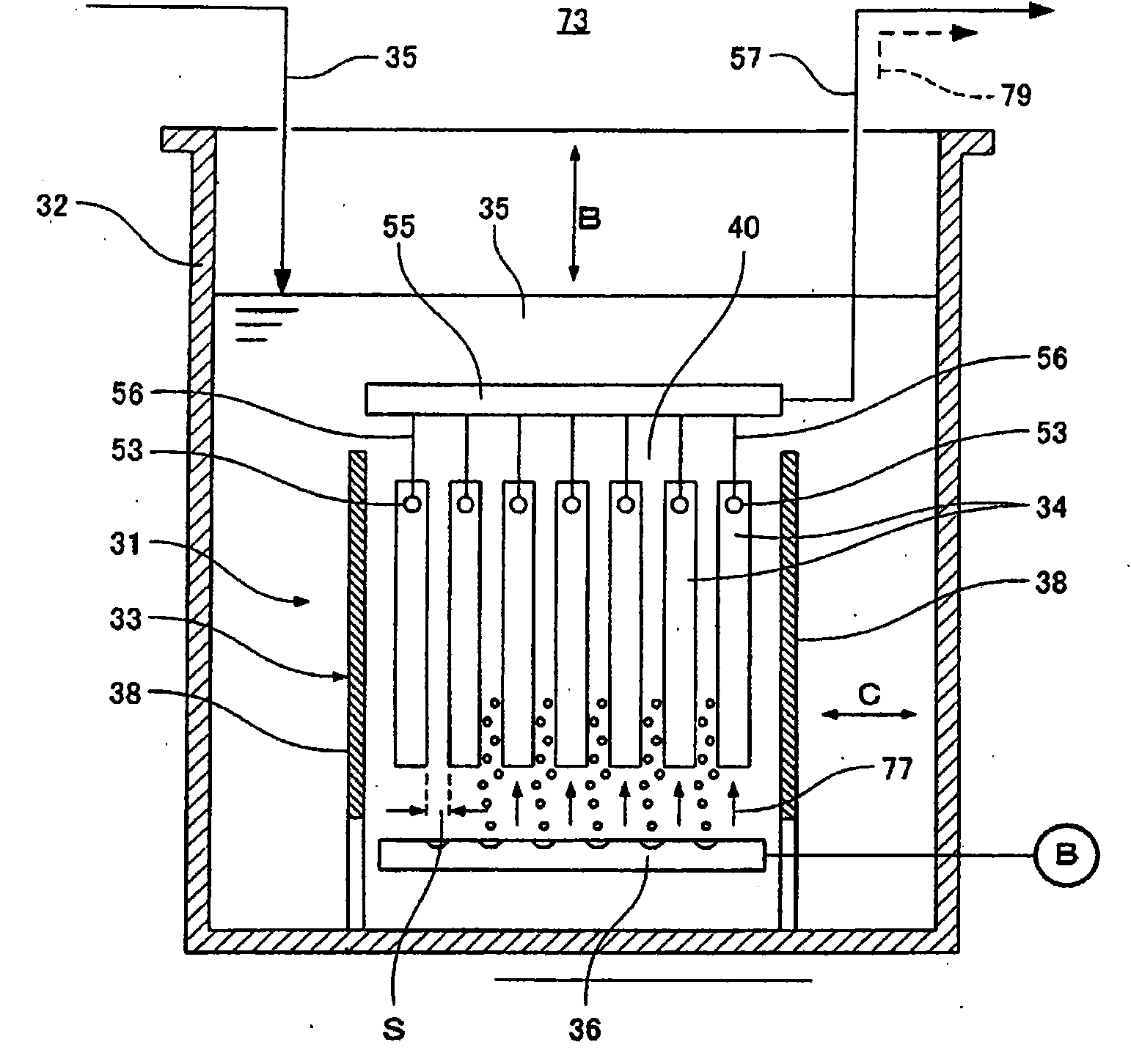
[0097] Such as figure 1 As shown, 31 is a submerged membrane separation device. This submerged membrane separation device 31 is immersed in a treatment tank 32 and is used to separate activated sludge and treated water. The submerged membrane separation device 31 has a box-shaped membrane casing 33 with upper and lower openings, a plurality of flat-plate-shaped membrane boxes 34 arranged in parallel to each other inside the casing 33, and arranged below these membrane boxes 34. The air diffuser 36.
[0098] In addition, the air diffusion device 36 is an example of a liquid flow generating device that generates a rise along the membrane surface of the diaphragm case 34 by ejecting air from a plurality of ejection holes formed in the air diffusion pipe. Flow 77 (an example of liquid flow in one direction).
[0099] Such as figure 2 , image 3 As shown, in the inst...
PUM
 Abstract
Description
Claims
Application Information
 - R&D Engineer
- R&D Manager
- IP Professional
- Industry Leading Data Capabilities
- Powerful AI technology
- Patent DNA Extraction
Browse by: Latest US Patents, China's latest patents, Technical Efficacy Thesaurus, Application Domain, Technology Topic, Popular Technical Reports.
© 2024 PatSnap. All rights reserved.Legal|Privacy policy|Modern Slavery Act Transparency Statement|Sitemap|About US| Contact US: help@patsnap.com