Eureka AIR delivers breakthrough ideas for toughest innovation challenges, trusted by R&D personnel around the world.

Thin-film magnetoresistive sensor

A magnetoresistive sensor and thin film technology, applied in the sensor field, can solve the problems affecting sensor performance, limiting chip design, limited bias magnetic field, etc., to achieve the effects of improving measurement accuracy and linearity process, low manufacturing cost, and high corresponding frequency

Active Publication Date: 2010-10-27
王建国 +1
View PDF0 Cites 17 Cited by
  • Summary
  • Abstract
  • Description
  • Claims
  • Application Information

AI Technical Summary

Problems solved by technology

[0005] The characteristics of the first method are: the process is simple, but the bias magnetic field provided by the shape anisotropy is limited, and it limits the design of the chip
The characteristic of the second method is that the size of the bias magnetic field can be changed by adjusting the composition and thickness of the permanent magnetic film, but in practical applications, it is necessary to avoid the interference of a large external magnetic field. If there is interference of a large magnetic field, the bias will be changed. The direction of the magnetic field, which affects the performance of the sensor
The characteristic of the third method is that the size of the bias magnetic field can be adjusted by changing the size of the current, but the power consumption of the sensor will be large

Method used


Image

  • Thin-film magnetoresistive sensor
  • Thin-film magnetoresistive sensor
  • Thin-film magnetoresistive sensor

Examples


Embodiment Construction

[0017] The present invention will be further described below in conjunction with specific drawings and embodiments.

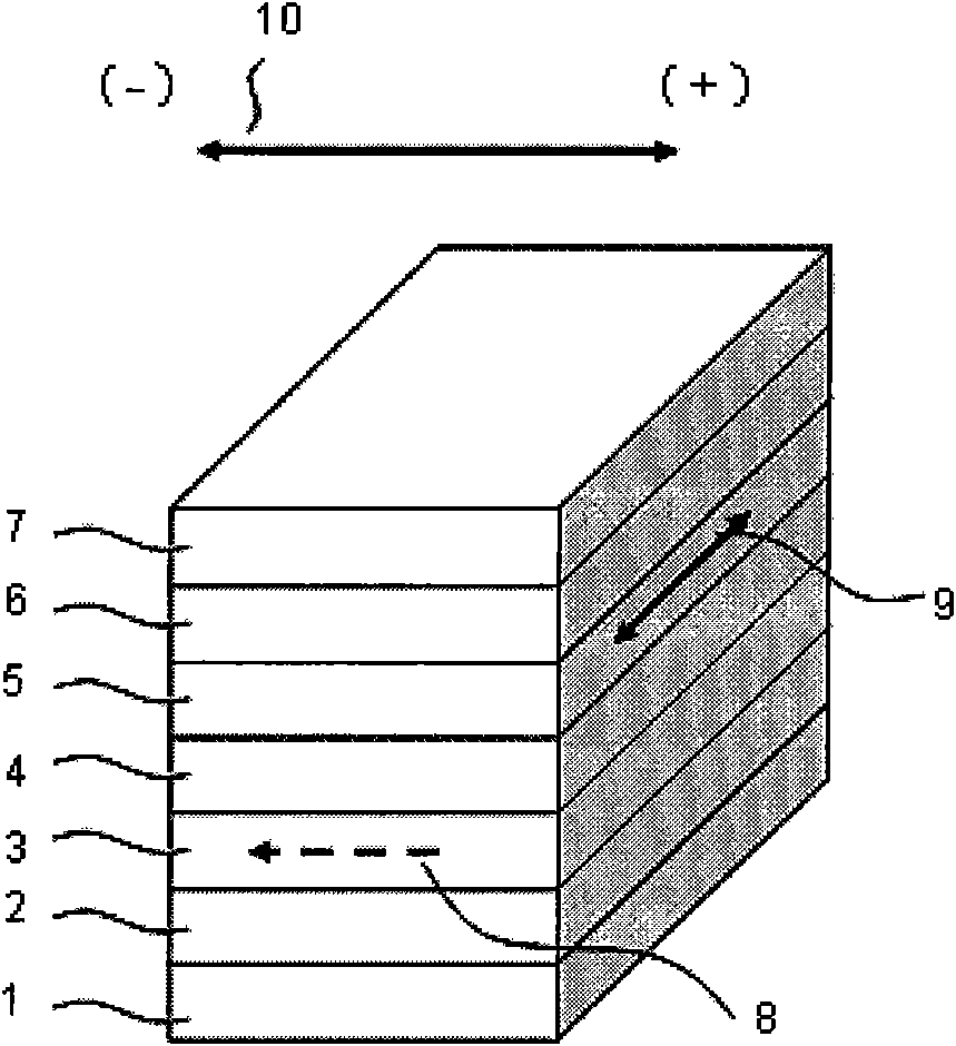
[0018] Such as figure 1 Shown: the present invention includes a seed layer 1, a first nonmagnetic pinned layer 2, a first magnetic pinned layer 3, a nonmagnetic spacer layer 4, a second magnetic pinned layer 5, a second nonmagnetic pinned layer 6 and protective layer 7.

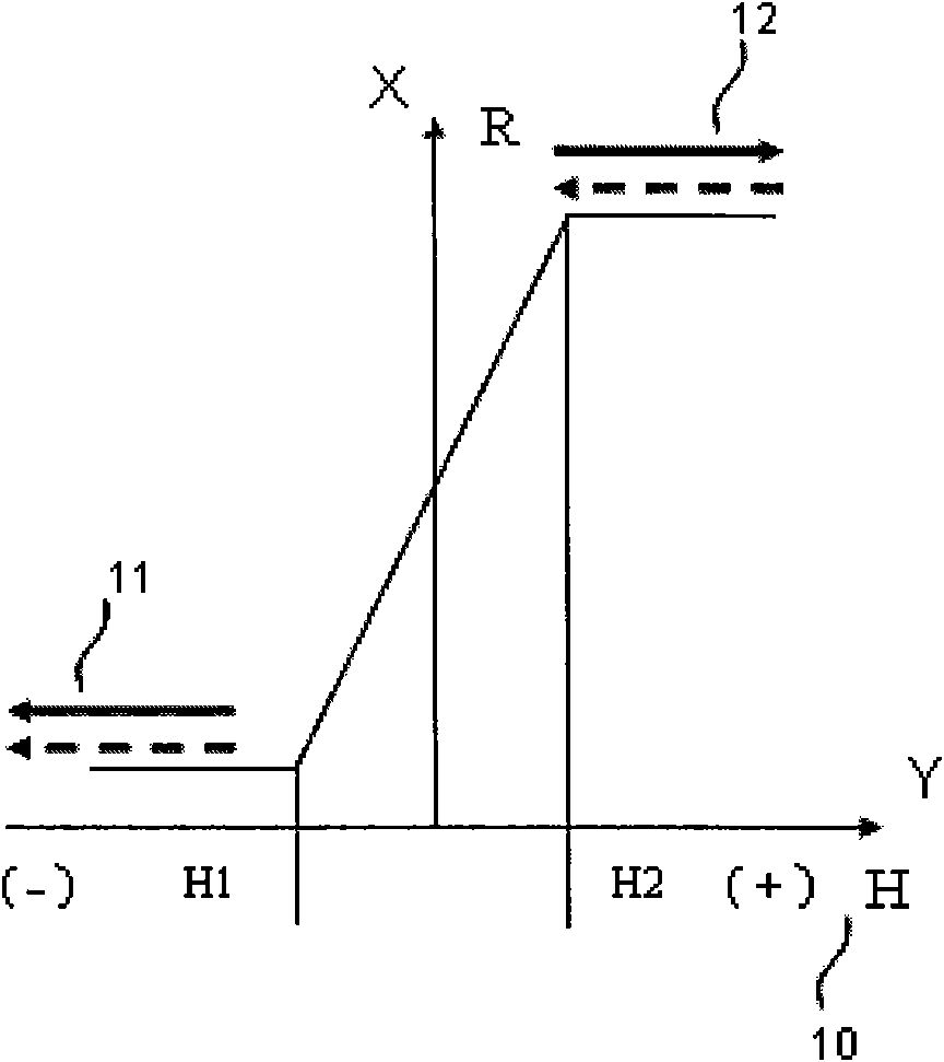
[0019] Such as figure 1 As shown, the seed layer 1 is provided with a first non-magnetic pinning layer 2, and the first non-magnetic pinning layer 2 is provided with a first magnetic pinned layer 3; Layer 3 and the first non-magnetic pinning layer 2 form a reference layer, and generate a first exchange coupling field; the direction of magnetic moment of the reference layer generating the first exchange coupling field is shown in 8 . A non-magnetic spacer 4 is disposed on the first magnetic pinned layer 3, and the material of the non-magnetic spacer 4 can be Cu, AlO, MgO, HFO, ZrO or TaO. T...


PUM


Abstract

The invention relates to a sensor, and particularly relates to thin-film magnetoresistive sensor, in particular to a sensor used for the equivalent detection of current, the position, the movement angle and the angular speed in a magnetic field. According to the technical scheme provided by the invention, the thin-film magnetoresistive sensor comprises a seed layer, a reference layer, a non-magnetic isolation layer and a free layer, wherein the reference layer is positioned on the seed layer and generates a first exchange coupling field; the non-magnetic isolation layer is positioned on the reference layer and isolates the reference layer and the free layer; and the free layer is positioned on the non-magnetic isolation layer, inducts the change of an external magnetic field and generates a second exchange coupling field, and the second exchange coupling field and the first exchange coupling field are mutually vertical. The invention has small hysteresis, high measurement accuracy and linearity, adjustable linear range, simple manufacturing process, high response frequency, low manufacturing cost and strong anti-jamming capability.

Description

technical field [0001] The invention relates to a sensor, especially a thin-film magnetoresistive sensor, in particular to a sensor used for detecting current, position, moving angle and angular velocity in a magnetic field. Background technique [0002] Thin film magnetoresistive sensors are widely used in data storage (computer hard disk, MRAM), current measurement, position measurement, moving speed, angle and angular velocity of objects and other measurement fields. [0003] Thin film magnetoresistive sensors have a multilayer film structure and a spin valve structure. The multi-layer film structure of the thin film magnetoresistive sensor includes magnetic layers and non-magnetic layers, which are alternately deposited on the substrate. The spin valve structure of described thin film magnetoresistive sensor comprises non-magnetic pinning layer (its material comprises MnIr or MnPt), magnetic pinned layer (its material comprises CoFeB or CoFe, or SAF structure CoFe / Ru / Co...

Claims


Application Information

Patent Timeline
Patent Type & Authority Applications(China)
IPC IPC(8): G01D5/14G01R33/09
Inventor 王建国薛松生
Owner 王建国
Why Eureka
Eureka Blog
Learn More