
Method and structure for testing semiconductor field effect transistor

A technology of field effect transistors and test structures, which is applied in the direction of single semiconductor device testing, semiconductor devices, measuring devices, etc., can solve the problems of reducing the accuracy of testing MOSFETs, electrical characteristic parameters and mismatch parameter errors, etc., to avoid parasitic resistance, The effect of improving accuracy

Inactive Publication Date: 2010-10-20
SEMICONDUCTOR MANUFACTURING INTERNATIONAL (BEIJING) CORP
View PDF5 Cites 19 Cited by
  • Summary
  • Abstract
  • Description
  • Claims
  • Application Information

AI Technical Summary

Problems solved by technology

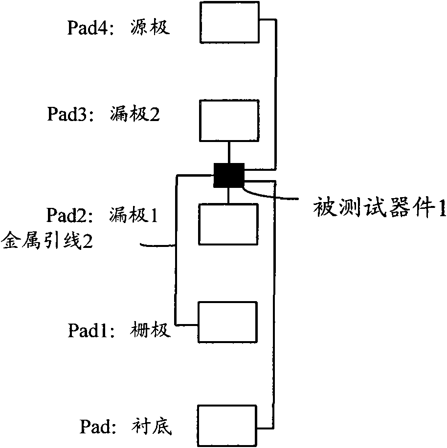
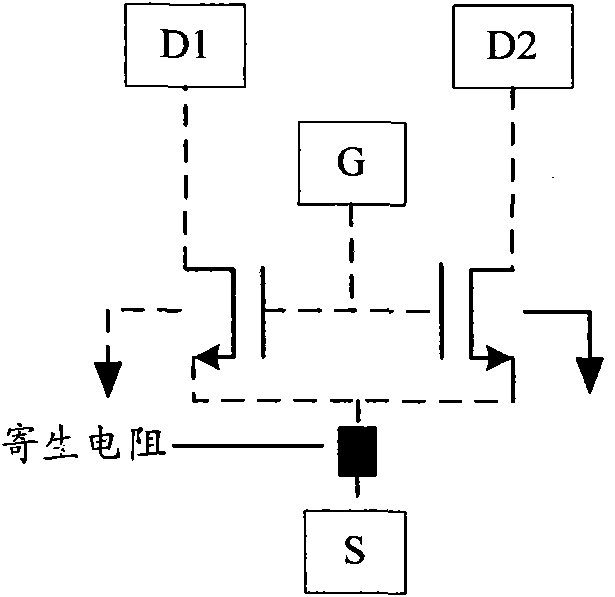
[0009] Further, due to the parasitic resistance Rs between the pad of the MOSFET source and the metal lead 2 between the tested device MOSFET, the electrical characteristic parameters and mismatch parameters obtained by the test calculation, and the electrical characteristic parameters and the mismatch parameters of the MOSFET in actual work There are errors in the mismatch parameters, which reduces the accuracy of testing MOSFETs

Method used


Image

  • Method and structure for testing semiconductor field effect transistor
  • Method and structure for testing semiconductor field effect transistor
  • Method and structure for testing semiconductor field effect transistor

Examples


Embodiment Construction

[0030] In order to make the object, technical solution and advantages of the present invention clearer, the present invention will be further described in detail below with reference to the accompanying drawings and examples.

[0031] It can be seen from the prior art that the reason for the inaccuracy of the MOSFET test is because figure 1 The test structure shown has a parasitic resistance Rs on the metal lead between the MOSFET source pad and the MOSFET under test, so the Idsat of the tested MOSFET is smaller than the actual one, and the threshold voltage is larger than the actual one. Therefore, the electrical characteristic parameters and mismatch parameters of the finally obtained MOSFET test are inaccurate. In order to overcome this defect, the present invention resets the test structure of the MOSFET, which avoids the parasitic resistance on the metal lead between the source of the MOSFET and the MOSFET of the device under test.

[0032] image 3It is a schematic dia...


PUM


Abstract

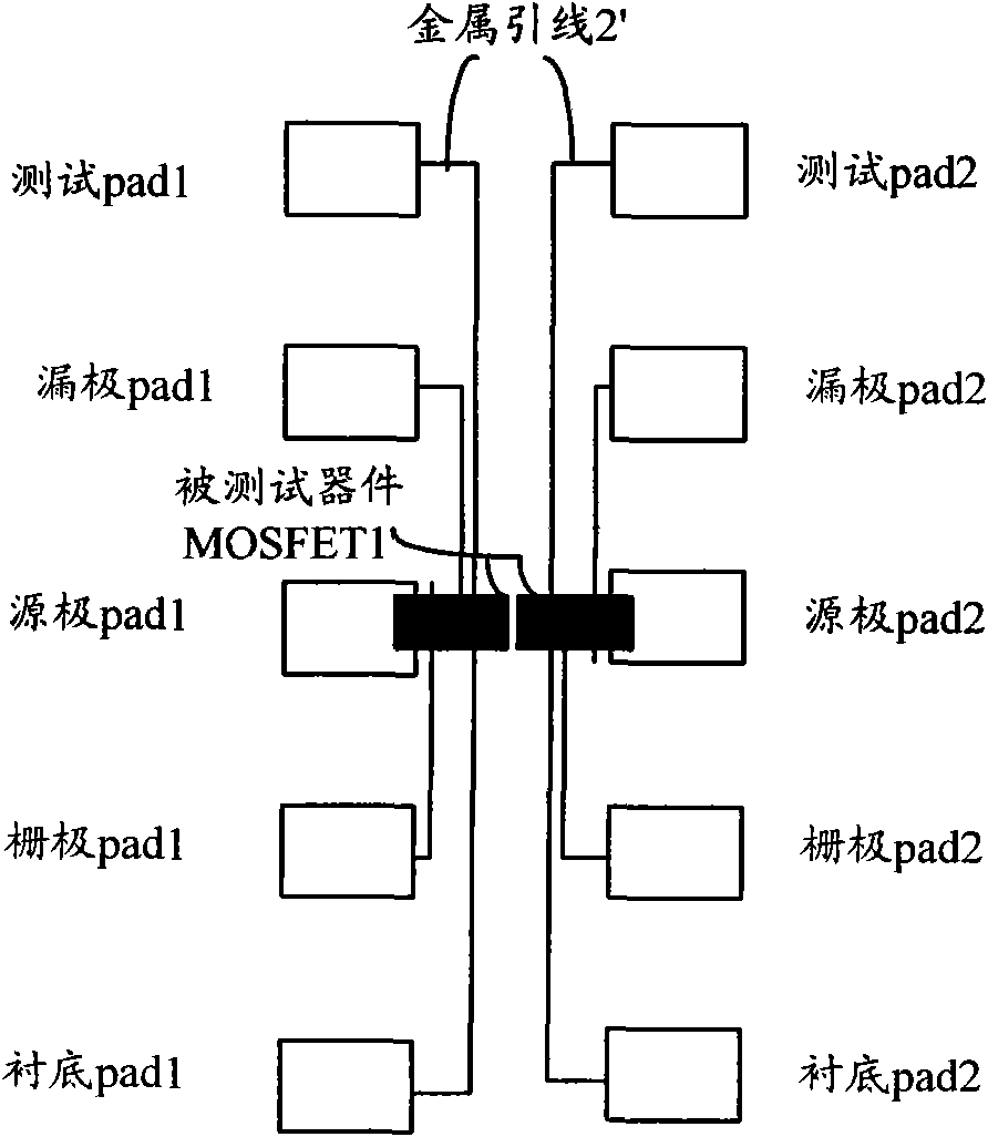
The invention discloses a structure for testing a metal-oxide-semiconductor field effect transistor (MOSFET), which is used for testing the MOSFET through a joint pad introduced from the MOSFET by a testing platform. The structure comprises the MOSFET and a metal lead, wherein two source electrode pads of the MOSFET are respectively and directly led out from two source electrodes of the MOSFET, two drain electrode pads of the MOSFET are respectively and directly led out from two drain electrodes of the MOSFET1 through metal leads, two grid electrode pads of the MOSFET are respectively and directly led from two grid electrodes of the MOSFET through metal leads, and two substrate pads are led out from an element substrate of the MOSFET through metal leads. The testing method and the testing structure improve the accuracy on testing the MOSFET.

Description

technical field [0001] The invention relates to the technical field of semiconductor manufacturing, in particular to a testing method and testing structure of a semiconductor field effect transistor (MOSFET). Background technique [0002] Currently, when testing MOSFETs, such as figure 1 The test structure shown is composed of a device under test 1 and metal leads 2 . The device under test 1 leads to a plurality of test contact pads (pads), and these contact pads can be connected to a test machine, so that the test machine can test the MOSFET through these pads. Among them, these pads include pad2 for testing MOSFET drain 1 and pad3 for testing MOSFET drain 2 directly from the MOSFET; pad1 for testing MOSFET gate, pad4 for testing MOSFET source and testing MOSFET device lining are respectively drawn out through metal leads 2. bottom pad. The test machine makes electrical contact with the pads led out of the device under test 1, applies a corresponding voltage or current t...

Claims


Application Information

Patent Timeline
IPC IPC(8): G01R31/26G01R19/00
CPCH01L2924/0002
Inventor 沈良邵芳黄威森
Owner SEMICONDUCTOR MANUFACTURING INTERNATIONAL (BEIJING) CORP
Learn More