
Thermal barrier coating layer high-temperature resistance molten salt corrosion test method and device

A technology of molten salt corrosion and thermal barrier coating, applied in measurement devices, weather resistance/light resistance/corrosion resistance, instruments, etc. The test time is arbitrarily controllable and the structure is simple.

Inactive Publication Date: 2010-10-20
SHANGHAI UNIV OF ENG SCI
View PDF4 Cites 8 Cited by
  • Summary
  • Abstract
  • Description
  • Claims
  • Application Information

AI Technical Summary

Problems solved by technology

Therefore, the existing test methods have the following defects: first, the solid or liquid corrosion salt is directly brushed or sprayed on the surface of the sample, and the reheating method cannot truly simulate the high temperature of the molten salt in the actual application of the thermal barrier coating. In the case of vapor form corrosion
Second, the test requires multiple cycle stages, and a certain amount of corrosion salt is artificially painted or sprayed. After each wash, it is difficult to ensure that the same amount will be applied next time, that is, each cycle cannot be guaranteed to be at the same level. Under the condition
Third, use boiling water or distilled water to scrub the residual salt after corrosion. During this process, a small part of the surface of the sample may be ground off, which may cause certain other effects on the sample. Authenticity causes great error

Method used


Image

  • Thermal barrier coating layer high-temperature resistance molten salt corrosion test method and device
  • Thermal barrier coating layer high-temperature resistance molten salt corrosion test method and device
  • Thermal barrier coating layer high-temperature resistance molten salt corrosion test method and device

Examples


Embodiment Construction

[0025] The working principle of the present invention and the method of use are further described below in conjunction with the accompanying drawings of the embodiments:

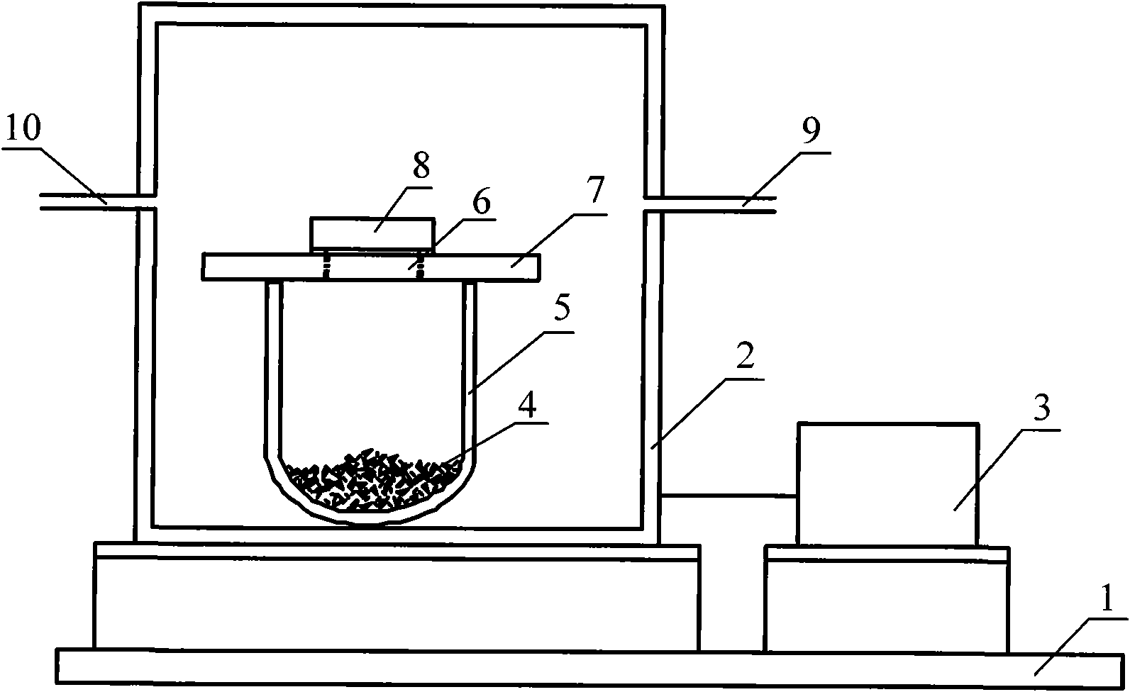
[0026] Please refer to the attached figure 1 , this is the test method and device layout of the thermal barrier coating against high temperature molten salt corrosion described in the present invention. On the working platform 1, the closed cavity type heating furnace 2 described in the present invention is set. A crucible 5 with corrosion salt powder 4 is arranged in the heating furnace 2 , and an electric heater controlled by a temperature controller 3 is arranged at the bottom of the crucible 5 .

[0027] The temperature rise and fall and constant temperature control in the heating furnace cavity are realized by the temperature controller 3 connected with the electric heater in the heating furnace 2 . The temperature controller 3 of this embodiment adopts XMT artificial intelligence precision controller ...


PUM


Abstract

The invention belongs to the coating layer material test technology, in particular to a thermal barrier coating layer high-temperature resistance molten salt corrosion test method and a device. Under the conditions of high temperature and constant temperature, when a test sample block reaches the set unit corrosion time, the test sample block is taken out for to be directly weighed and recorded, the periodic process of high-temperature molten salt steam corrosion, weighing and recording of the test sample block is cyclically carried out until cracks occur on the sample block, and the test and data collection period is completed. The thermal barrier coating layer high-temperature resistance molten salt corrosion test device designed by aiming at the test method has the advantages of simple structure and convenient operation, the test temperature is adjustable and is above the molten salt melting point, and the test time is arbitrary and controllable. The invention adopts the molten salt steam corrosion test sample block, and then adopts a method of directly taking out the molten salt steam corrosion test sample block to be weighed and recorded, the defects of the prior art are overcome, the test results are obtained, and the invention can reflect the molten salt steam corrosion resistance capability of the thermal barrier coating layer in actual high-temperature service.

Description

technical field [0001] The invention belongs to thermal barrier coating testing technology, in particular to a testing method and device for thermal barrier coating resistance to high-temperature molten salt corrosion. Background technique [0002] Thermal barrier coatings (TBCs) are currently one of the most advanced high-temperature protective coatings. They have superior properties such as high-temperature corrosion resistance, high-temperature oxidation resistance, and good heat insulation effects. It can improve the working life of the engine, improve fuel combustion efficiency, and improve engine performance. Therefore, it plays an important role in the fields of aviation, ships, and energy. The high temperature corrosion resistance test of thermal barrier coatings is one of the key topics in the research and development process. [0003] Since the fuel oil used by the gas turbine engine inevitably contains Na, S, V and other impurities, and Na 2 SO 4 , V 2 o 5 Th...

Claims


Application Information

Patent Timeline
IPC IPC(8): G01N17/00
Inventor 李志明钱士强王伟黄晨
Owner SHANGHAI UNIV OF ENG SCI
Learn More