
Generator with continuous variable volume compression ratio

A volume compression and engine technology, applied in engine control, machine/engine, mechanical equipment, etc., can solve problems such as few achievements, complex structure, and difficulty in mass production, so as to save fuel, reduce vehicle weight, and improve air intake The effect of charging

Inactive Publication Date: 2010-10-20
高伟
View PDF5 Cites 14 Cited by
  • Summary
  • Abstract
  • Description
  • Claims
  • Application Information

AI Technical Summary

Problems solved by technology

[0004] At present, the research on variable compression ratio engines is relatively common in foreign countries, but there are relatively few achievements that can realize the function of variable compression ratio, and the structure is complicated, so it is not easy to mass-produce

Method used


Image

  • Generator with continuous variable volume compression ratio
  • Generator with continuous variable volume compression ratio
  • Generator with continuous variable volume compression ratio

Examples


Embodiment Construction

[0024] The present invention will be further described below in conjunction with the drawings and embodiments.

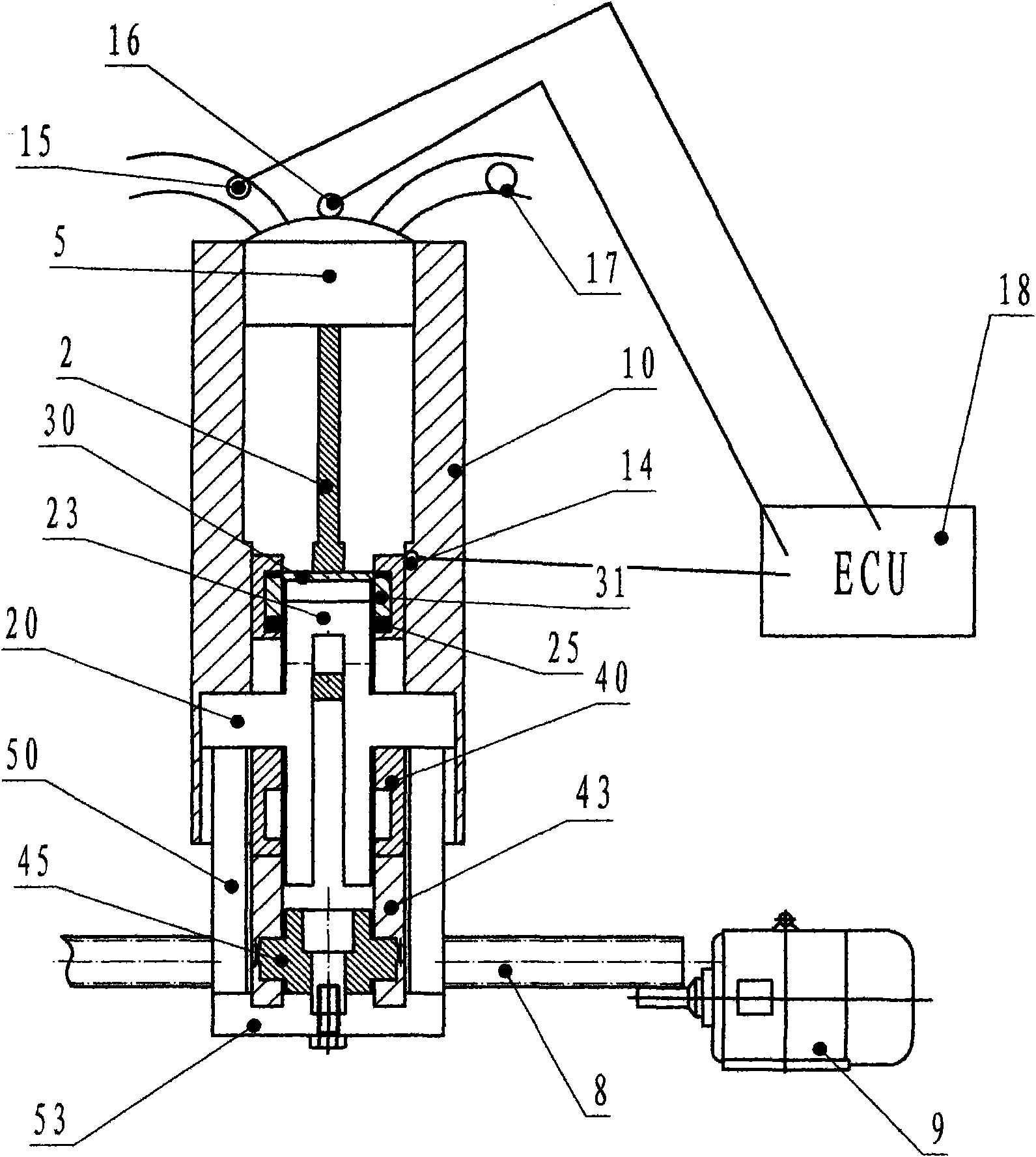
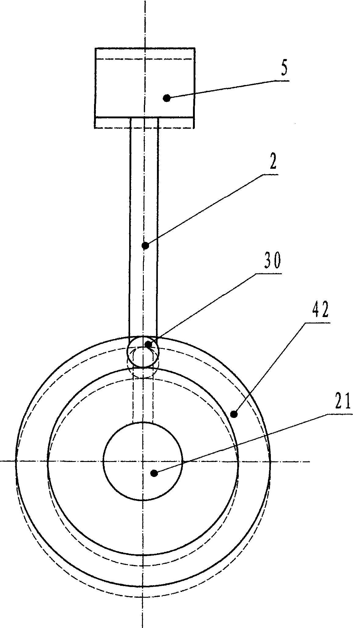
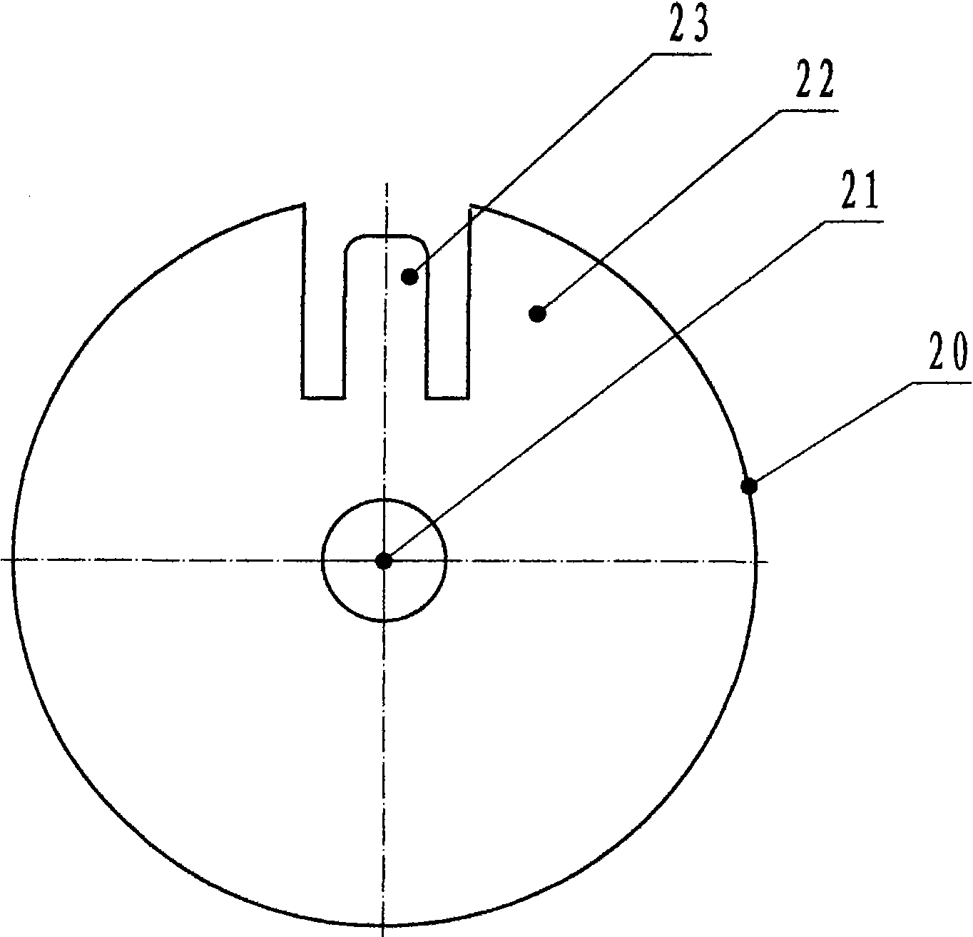
[0025] Reference figure 1 , The continuously variable volume compression ratio engine of the present invention includes a sensor, a box body 10, a crankshaft 20, and at least one connecting rod 2 and a piston 5 whose one end is rotatably connected with an outer journal sleeve 30 mounted on the journal 23 The journal 23 of the crankshaft 20 is provided with a continuously variable volume compression ratio mechanism; the variable compression ratio mechanism is controlled by the ring track body 40 installed in the box body 10; the box body 10 is provided with a fixing mechanism, The fixing mechanism is provided with a control mechanism for a continuously variable volume compression ratio engine. The ring orbit body 40 is controlled by the control mechanism to control the position of the outer journal sleeve 30 at the top dead center, thereby changing the position of the pi...


PUM


Abstract

The invention discloses a generator with continuous variable volume compression ratio, comprising a sensor, a box body, a bent axle, at least one connecting rod and a piston, wherein one end of the connecting rod is rotatablely connected with an outer shaft cervical collar installed on a shaft neck; the shaft neck of the bent axle is provided with a continuous variable volume compression ratio mechanism which is controlled by a circular ring orbit installed in the box body; a fixed mechanism which is arranged on the box body is provided with the control mechanism of the generator with the continuous variable volume compression ratio; the control mechanism controls the circular ring orbit to control different positions for the outer shaft cervical collar to be sheathed on an upper dead center and a lower dead center to realize different compressed heights and compression ratio so as to improve fuel economy and dynamic property.

Description

Technical field [0001] The invention relates to a variable reduction ratio technology of an engine, which can allow different compression ratios to be realized by controlling the different compression heights of the piston at the top dead center. Background technique [0002] With the increasingly stringent emission regulations and customer requirements for engine economy, improving engine emission performance and fuel economy has become the biggest difficulty faced by traditional internal combustion engines. Now engines mainly use three-way catalysts to change emissions, and to improve fuel economy, they mainly use in-cylinder direct injection and variable valve technology. In order to further reduce emissions, many new combustion modes have now emerged. These new combustion modes mainly pursue low-temperature combustion and the formation of homogeneous mixtures, which require low charge temperature and uniform mixtures, as well as lower compression ratios to reduce NOX and PM ...

Claims


Application Information

Patent Timeline
Patent Type & Authority Applications(China)
IPC IPC(8): F02B75/04F02D15/02
Inventor 高伟
Owner 高伟
Learn More