
High-pressure material angle valve with turbulence blades

A technology of turbulent blades and angle valves, which is applied in the direction of valve energy absorption devices, valve details, valve devices, etc., can solve the problems of slow development of material angle valves, reduced product service life, high production costs, etc., and achieve product quality The structure is simple, the service life is prolonged, and the effect of reducing erosion

Active Publication Date: 2010-10-13
WUXI SMART AUTO CONTROL ENG CO LTD
View PDF7 Cites 1 Cited by
  • Summary
  • Abstract
  • Description
  • Claims
  • Application Information

AI Technical Summary

Problems solved by technology

[0002] With the continuous improvement of the domestic industrial automation level, the control valve, as the most commonly used and most important terminal control element in process control, has a very fast overall development speed, but the development speed of material angle valves for harsh working conditions such as high temperature and high pressure difference However, it is relatively slow. Most of the internal parts of high-pressure material angle valves are severely worn due to the erosion of high-speed medium flow, which greatly reduces the service life of the product and brings huge economic losses.
At present, the pressure reduction and noise reduction methods commonly used for high-pressure material angle valves generally adopt the installation of throttling sleeves, labyrinth groups, etc. Although the use effect of some products is ideal, the production cost is too high

Method used


Image

  • High-pressure material angle valve with turbulence blades
  • High-pressure material angle valve with turbulence blades
  • High-pressure material angle valve with turbulence blades

Examples


Embodiment Construction

[0013] The present invention will be further described below in conjunction with specific drawings and embodiments.

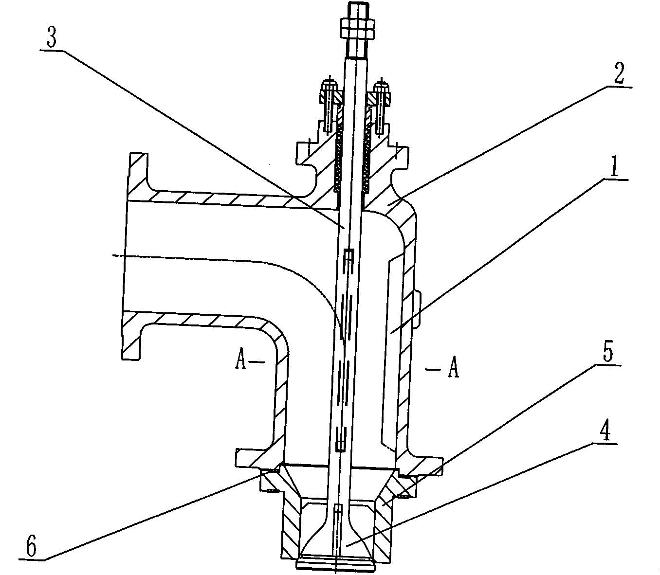
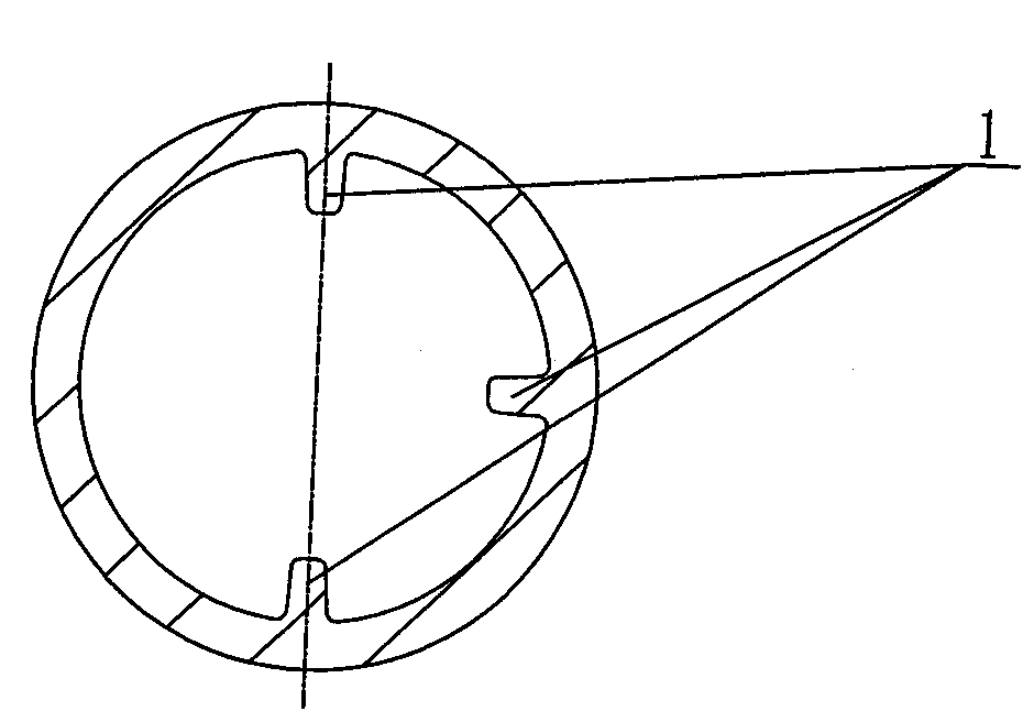
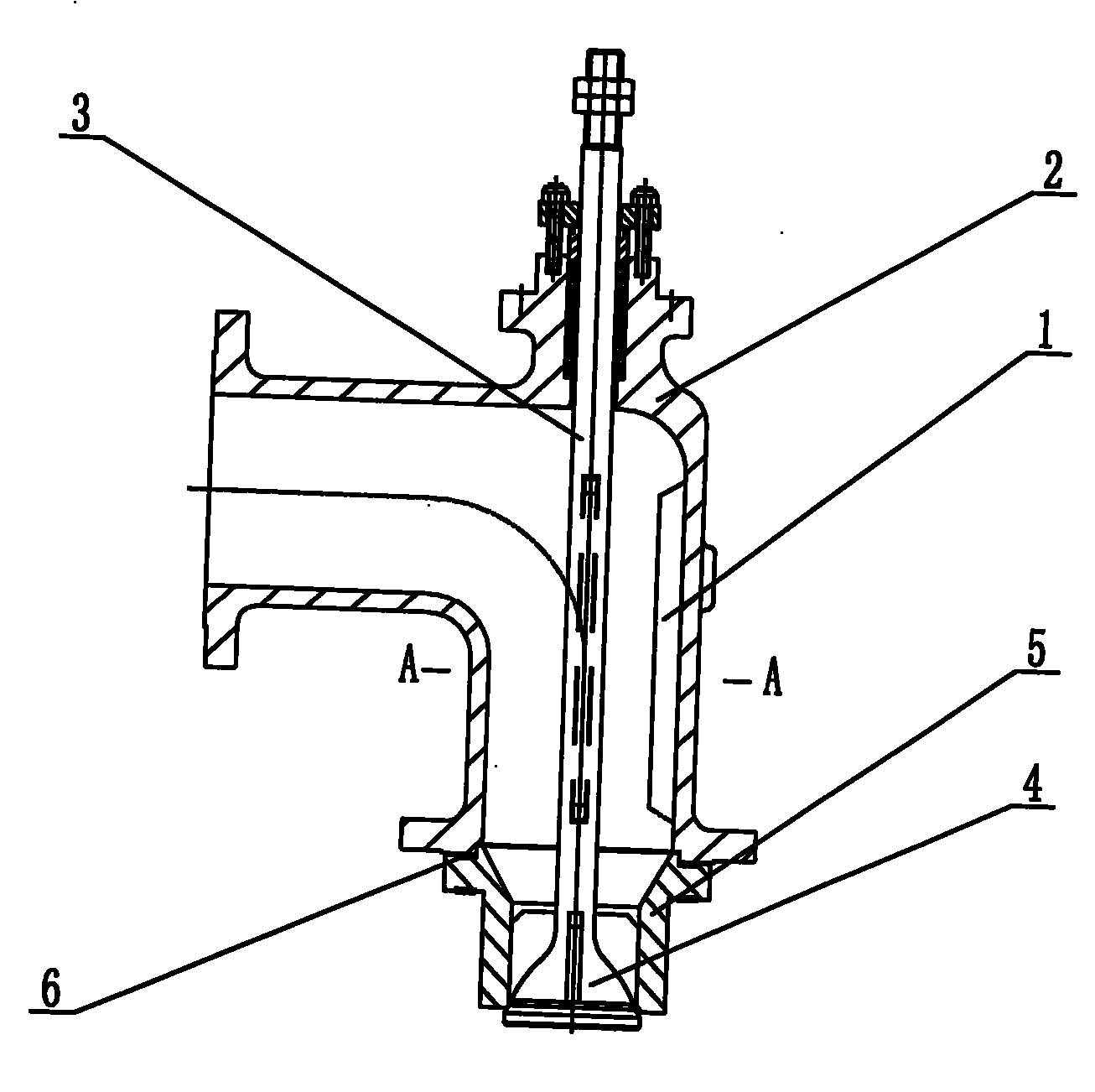
[0014] Such as Figure 1 ~ Figure 2 As shown: the high-pressure material angle valve with spoiler vane includes spoiler vane 1, angle valve body 2, valve stem 3, valve core 4, valve seat 5, sealing gasket 6, etc.

[0015] The present invention comprises angle valve valve body 2, and described angle valve valve body 2 is right angle type, is provided with valve seat 5 at the outlet of angle valve valve body 2; Valve stem 3 is housed in angle valve body 2, valve stem 3 and The valve core 4 has an integrated structure, the top of the valve stem 3 passes through the angle valve body 2, the valve core 4 is installed in the valve seat 5, and the valve seat 5 and the angle valve body 2 are sealed with a gasket 6; Angle valve body 2 is provided with spoiler blades 1, and the spoiler blades 1 are respectively arranged on the inner cavity wall directly opposite to the i...


PUM


Abstract

The invention relates to a high-pressure material angle valve with turbulence blades, which comprises a valve body of the angle valve, wherein the valve body of the angle valve is right angle type, a valve seat is arranged at an outlet of the valve body of the angle valve, and a valve core is mounted in the valve seat; a valve rod is mounted in the valve body of the angle valve, the valve rod andthe valve core constitute an integrated structure, and the top end of the valve rod penetrates out of the valve body of the angle valve; and the high-pressure material angle valve is characterized inthat the turbulence blades are arranged on the wall of an inner cavity of the valve body of the angle valve. The turbulence blades are respectively arranged on the wall of the inner cavity which is just opposite to an inlet of the valve body of the angle valve, the wall of the inner cavity on the left side surface and the wall of the inner cavity on the right side surface. A sealing gasket is utilized for sealing between the valve seat and the outlet of the valve body of the angle valve. The high-pressure material angle valve has the advantages of simple structure, safety and reliability, andcan greatly reduce the production cost.

Description

technical field [0001] The invention relates to a high-pressure material angle valve, in particular to a high-pressure material angle valve with spoiler blades. Background technique [0002] With the continuous improvement of the domestic industrial automation level, the control valve, as the most commonly used and most important terminal control element in process control, has a very fast overall development speed, but the development speed of material angle valves for harsh working conditions such as high temperature and high pressure difference However, it is relatively slow. Most of the internal parts of high-pressure material angle valves are severely worn due to the erosion of high-speed medium flow, which greatly reduces the service life of the product and brings huge economic losses. At present, the pressure reduction and noise reduction methods commonly used for high-pressure material angle valves generally adopt the installation of throttle sleeves, labyrinth group...

Claims


Application Information

Patent Timeline
Patent Type & Authority Applications(China)
IPC IPC(8): F16K27/02F16K47/00
Inventor 陈彦张志超张程
Owner WUXI SMART AUTO CONTROL ENG CO LTD
Learn More