
Combined PNP-trench isolation RC-GCT component and preparation method thereof

A technology of RC-GCT and devices, which is applied in the manufacture of semiconductor/solid-state devices, semiconductor devices, electrical components, etc., can solve the problems of difficult manufacturing process and high cost, reduce the difficulty and cost of manufacturing process, and save the control of the minority lifetime required effect

Active Publication Date: 2010-10-06
XIAN UNIV OF TECH
View PDF1 Cites 26 Cited by
  • Summary
  • Abstract
  • Description
  • Claims
  • Application Information

AI Technical Summary

Problems solved by technology

[0004] The purpose of the present invention is to provide a pnp-trench compound isolation RC-GCT device, which solves the problems of difficult and high cost in the manufacturing process of the existing RC-GCT device, and not only has reliable commutation characteristics, but also saves Minority carrier lifetime control requirements for PIN diodes

Method used


Image

  • Combined PNP-trench isolation RC-GCT component and preparation method thereof
  • Combined PNP-trench isolation RC-GCT component and preparation method thereof
  • Combined PNP-trench isolation RC-GCT component and preparation method thereof

Examples


Embodiment Construction

[0032] The present invention will be described in detail below in conjunction with the accompanying drawings and specific embodiments.

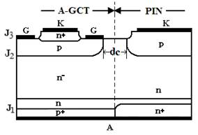
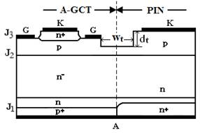
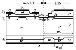
[0033] Fig. 1 is a comparison of the basic structure sections of the RC-GCT device of the present invention and the existing pnp isolation RC-GCT and trench isolation RC-GCT.

[0034] Figure 1a It is the structure diagram of the existing RC-GCT device. The pnp isolation method is adopted between the A-GCT and the PIN diode. No matter whether the voltage between G and K is positive or negative, there is always a pn junction in the pnp that is reverse-biased. Therefore, the pnp The essence of isolation is pn junction isolation, the leakage current is very small, and the isolation effect is very good. However, the pnp structure requires silicon nitride (Si 3 N 4 ) under the cover of the masking film is realized by the selective deep diffusion of p-type impurity aluminum, which makes the manufacturing process very difficult and the cost is al...


PUM


Abstract

The invention discloses a combined PNP-trench isolation RC-GCT (reverse conducting-gate commutated thyristor) component. The entire component is divided into an A-GCT (asymmetric gate commutated thyristor) and a PIN diode. The A-GCT is structurally characterized in that a wavelike P base region and a P+ base region are sequentially arranged in the upward direction of an N- region; an N+ cathode region is arranged on the upper surface of the middle section of the P+ base region, which corresponds to the wave crest of the wavelike P base region; a cathode aluminum electrode constitutes the upper surface of the N+ cathode region; gate aluminum electrodes are respectively arranged on the upper surfaces of the P+ base regions on two sides of the N+ cathode region; and an N buffer layer and a transparent P+ anode region are arranged in the downward direction of the N- region. The PIN diode is structurally characterized in that a P base region and a P+ base region are sequentially arranged in the upward direction of an N- region; a cathode aluminum electrode is arranged on the surface of the P+ base region; an N buffer layer is arranged in the downward direction of the N- region; and an N+ cathode region I of the PIN diode, a P+ short-circuit region and an N+ cathode region II of the PIN diode are arranged side by side below the N buffer layer. The invention further discloses a method for preparing the combined PNP-trench isolation RC-GCT component. The invention can effectively improve the characteristics of the PIN diode in reverse recovery, thus dispensing with the control on the minority carrier lifetime.

Description

technical field [0001] The invention belongs to the technical field of power semiconductor devices, and in particular relates to a pnp-trench composite isolation RC-GCT device, and also relates to a preparation method of the pnp-trench composite isolation RC-GCT device. Background technique [0002] Gate-commutated thyristor (GCT) is a new type of power semiconductor device, which is developed on the basis of gate-turn-off thyristor (GTO). The reverse conduction GCT (RC-GCT) integrates the asymmetric GCT (A-GCT) and the PIN diode in antiparallel on one chip, in which a transparent anode and a buffer layer are added to make the device conductive in both forward and reverse directions. ability. The whole device is packaged in a tube, and the device and its gate drive circuit are organically assembled together through a printed circuit board to form an integrated gate commutated thyristor (IGCT). It uses a "hard drive" circuit to turn the device on and off. Compared with th...

Claims


Application Information

Patent Timeline
IPC IPC(8): H01L29/744H01L29/08H01L21/332
Inventor 王彩琳
Owner XIAN UNIV OF TECH
Learn More