
Microwave heating device

A microwave heating device and microwave technology, applied in microwave heating and other directions, can solve problems such as the limitation of microwave supply flexibility

Inactive Publication Date: 2010-09-22
WHIRLPOOL CORP
View PDF5 Cites 16 Cited by
  • Summary
  • Abstract
  • Description
  • Claims
  • Application Information

AI Technical Summary

Problems solved by technology

[0004] The disadvantage of this technology is that two supply ports are required to provide stable field pattern and field matching, and there are limitations in the flexibility of microwave supply

Method used


Image

  • Microwave heating device
  • Microwave heating device
  • Microwave heating device

Examples


Embodiment Construction

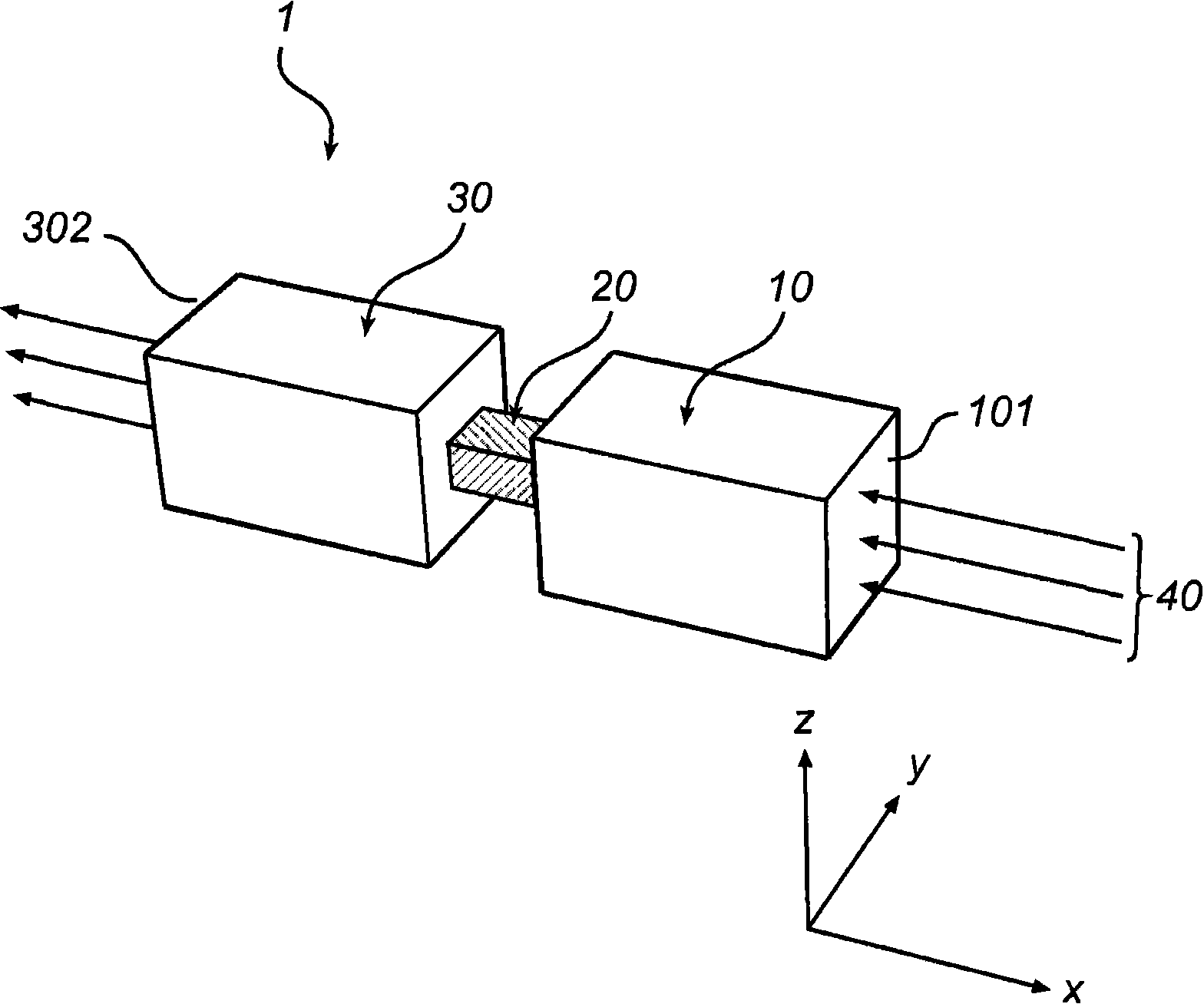
[0040] As an introduction to the concept of the present invention, figure 1 A waveguide structure including two gas-filled waveguides connected to each other via a resonator (or resonance waveguide) is shown.

[0041] figure 1 A waveguide structure 1 including a first gas-filled transmission line or waveguide 10, a resonator or resonant waveguide 20, and a second gas-filled transmission line or waveguide 30 is shown. The microwave 40 is supplied into the structure 1 at the first end or face 101 of the first gas-filled waveguide 10. The microwave propagates along the first transmission line 10 and the second transmission line 30 through the resonance waveguide 20 arranged at the junction between the first transmission line 10 and the second transmission line 30. The microwave leaves the waveguide structure 1 at the end 302 of the second transmission line 30, which is the end opposite to the end of the transmission line 30 adjacent to the resonant waveguide 20.

[0042] use for figu...


PUM


Abstract

A microwave heating device for heating a load by means of microwaves is provided. The microwave heating device (300) comprises a cavity (350) arranged to receive a load to be heated and a feeding structure (325) for feeding microwaves in the cavity. The feeding structure comprises a transmission line (330) for transmitting microwave energy generated by a microwave source (310) and a resonator (320) arranged at the junction between the transmission line and the cavity for operating as a feeding port (320a) of the cavity. The dielectric constant of the material constituting the interior of the resonator and the dimensions of the resonator are selected such that a resonance condition is established in the resonator for the microwaves generated by the source and impedance matching is established between the transmission line, the resonator and the cavity. In addition, the present invention provides a microwave heating device (500) comprising a plurality of feeding ports (525, 525') with reduced crosstalk.

Description

Technical field [0001] The invention relates to the field of microwave heating. Specifically, the present invention relates to a microwave heating device including a supply structure that enables the operation of the device to be substantially independent of the load to be heated. Background technique [0002] Microwave heating technology involves supplying microwave energy into the cavity. When heating loads in the form of foods, for example, by microwave heating equipment, many aspects must be considered. Most of these aspects are well known to those skilled in the art, including, for example, the desire to absorb the maximum amount of available microwave power in the food while achieving uniform heating of the food in order to achieve a satisfactory degree of efficiency. In particular, the operation of the microwave heating device is preferably independent or at least almost insensitive to the nature of the load to be heated. [0003] In European Patent EP0478053, a microwave...

Claims


Application Information

Patent Timeline
IPC IPC(8): H05B6/70H05B6/80
CPCH05B6/74
Inventor N·尤尔夫N·奥尔H·弗雷德里克C·哈坎
Owner WHIRLPOOL CORP
Learn More