Intelligent electric actuating mechanism

An electric actuator, intelligent technology, applied in the direction of AC motor control, electrical components, electronic commutator, etc., can solve the problems of no self-diagnosis function, poor reliability, difficult replacement, etc., achieve rich self-diagnosis function, easy to use Effects with maintenance and flexible configuration functions

Inactive Publication Date: 2010-09-22
昂踹克自动化仪表(上海)有限公司
View PDF5 Cites 6 Cited by
  • Summary
  • Abstract
  • Description
  • Claims
  • Application Information

AI Technical Summary

Problems solved by technology

Once the electric actuator in this way is installed, the speed can no longer be adjusted, which is not suitable for modern intelligent control
[0003] In addition, due to the need to adapt to different parameter requirements, the peripheral accessories of electric actuators often have a wide variety, and it is extremely difficult to replace them on site.
[0004] Traditional electric actuators generally use a combination of potentiometers and gears for stroke setting. Its structure is complex and its reliability is poor, and on-site users often cannot choose flexibly.
In terms of control functions, traditional electric actuators can only complete basic switching requirements, but cannot achieve complex judgments and operations, and do not have self-diagnosis functions
[0005] With the improvement of industrial technology, users have put forward higher requirements for the communication and network configuration capabilities of electric actuators, while traditional electric actuators basically do not have the industrial fieldbus capabilities at the international level in the late 1990s

Method used


Image

  • Intelligent electric actuating mechanism
  • Intelligent electric actuating mechanism

Examples


Embodiment Construction

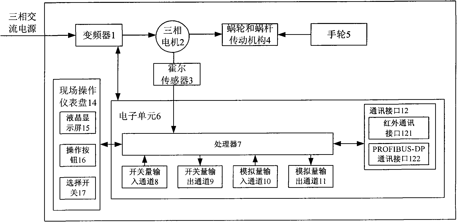
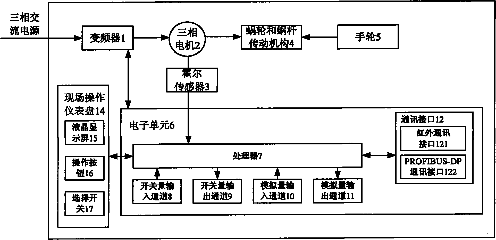
[0021] Such as figure 1 As shown, the intelligent electric actuator of the present invention includes a frequency converter 1 , a three-phase motor 2 , a Hall sensor 3 , a worm gear and a worm drive mechanism 4 , a hand wheel 5 , an electronic unit 6 and an on-site operation instrument panel 14 . Among them, the electronic unit 6 includes a microprocessor 7 , a switch input channel 8 , a switch output channel 9 , an analog input channel 10 , an analog output channel 11 , and a communication interface 12 . The communication interface 12 includes an infrared communication interface 121 and a PROFIBUS-DP communication interface 122 . The on-site operation instrument panel 14 includes a liquid crystal display 15 , operation buttons 16 and selection switches 17 .

[0022] Frequency converter 1 is used to control and adjust the motor speed and output torque. The three-phase motor 2 is used to drive the worm gear and the worm transmission mechanism 4 to move. Hall sensor 3 is used...


PUM


Abstract

The invention discloses an intelligent electric actuating mechanism, which comprises a transducer, a worm and gear transmission mechanism, a three-phase motor, an electronic unit, a Hall sensor, a hand wheel and an on-site operation instrument panel, wherein the transducer is used for controlling the operation direction and speed of the three-phase motor; the worm and gear transmission mechanism is used for driving a valve to operate; the three-phase motor is used for driving the worm and gear transmission mechanism to move; the electronic unit is used for controlling the operation of the transducer; the Hall sensor is used for sending a feedback signal to the electronic unit; the hand wheel is used for manually driving the worm and gear transmission mechanism to move; the on-site operation instrument panel is used for setting parameters; the transducer is connected with the electronic unit and the three-phase motor; the worm and gear transmission mechanism is connected with the three-phase motor and the hand wheel; and the electronic unit is connected with the on-site operation instrument panel and the Hall sensor. The intelligent electric actuating mechanism of the invention has a self diagnosis function, is convenient and quick in use and can realize remote monitoring and control.

Description

technical field [0001] The invention relates to an actuator, in particular to an intelligent electric actuator. Background technique [0002] The electric actuator is a common actuator, which can be widely used in the field of automation control. Electric actuators widely used in domestic industrial sites now generally use on-off mode to control single-phase or three-phase AC motors. Once the electric actuator using this method is installed, the speed can no longer be adjusted, which is not suitable for modern intelligent control. [0003] In addition, due to the need to adapt to different parameter requirements, the peripheral accessories of the electric actuator are often of various types, and it is extremely difficult to replace them on site. [0004] Traditional electric actuators generally use a combination of potentiometers and gears for stroke setting. Its structure is complex and its reliability is poor, and on-site users often cannot choose flexibly. In terms of ...

Claims


Application Information

Patent Timeline
Patent Type & Authority Applications(China)
IPC IPC(8): G05B19/04H02P27/04H02P6/16H02P25/02
Inventor 翟冬青
Owner 昂踹克自动化仪表(上海)有限公司
Why Eureka
Try Eureka