Eureka AIR delivers breakthrough ideas for toughest innovation challenges, trusted by R&D personnel around the world.

Road surface deceleration strip vehicle-mounted early warning device

A technology of early warning device and speed bump, applied in signal devices, vehicle parts, transportation and packaging, etc., can solve the problems of human cervical vertebra injury, speed bump to vehicle damage, affecting the comfort of drivers and occupants, etc., to increase the sense of safety. , The effect of easy installation and simple structure

Inactive Publication Date: 2010-09-22
HUNAN UNIV OF SCI & TECH
View PDF7 Cites 10 Cited by
  • Summary
  • Abstract
  • Description
  • Claims
  • Application Information

AI Technical Summary

Problems solved by technology

Although speed bumps have undergone a long process of continuous improvement, it has been found through practical application that they still have the following common problems: affecting the comfort of the driver and passengers, and in severe cases can cause damage to the human cervical spine and other parts; the speed bumps cause damage to the vehicle, Excessive speed may cause serious traffic accidents such as overturning; the noise generated during the use of speed bumps, especially when heavy vehicles pass by, has a negative impact on the lives of surrounding residents
[0004] How to solve the above problems so as to make better use of speed bumps as a traffic facility, governments, experts and scholars of various countries have done a lot of work, mainly focusing on optimizing the structure and layout of speed bumps, and research on the detection and early warning system of speed bumps a bit less

Method used


Image

  • Road surface deceleration strip vehicle-mounted early warning device
  • Road surface deceleration strip vehicle-mounted early warning device
  • Road surface deceleration strip vehicle-mounted early warning device

Examples


Embodiment Construction

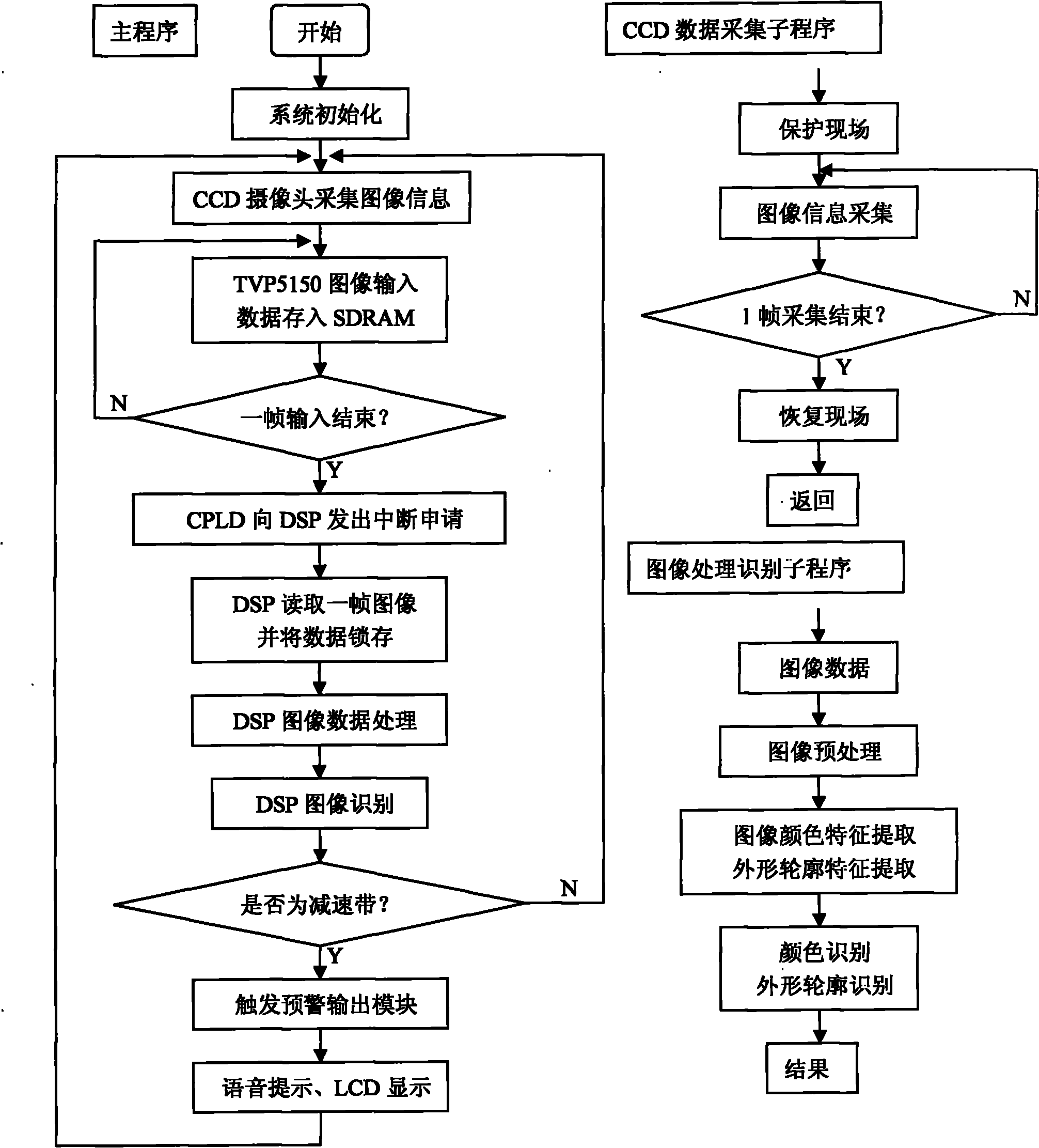
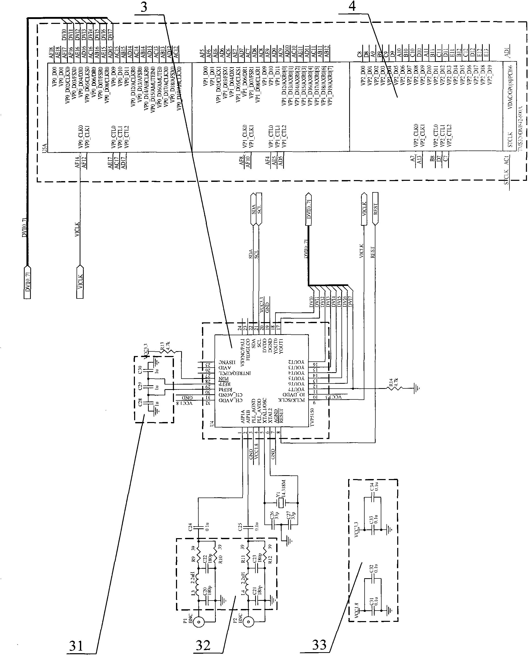
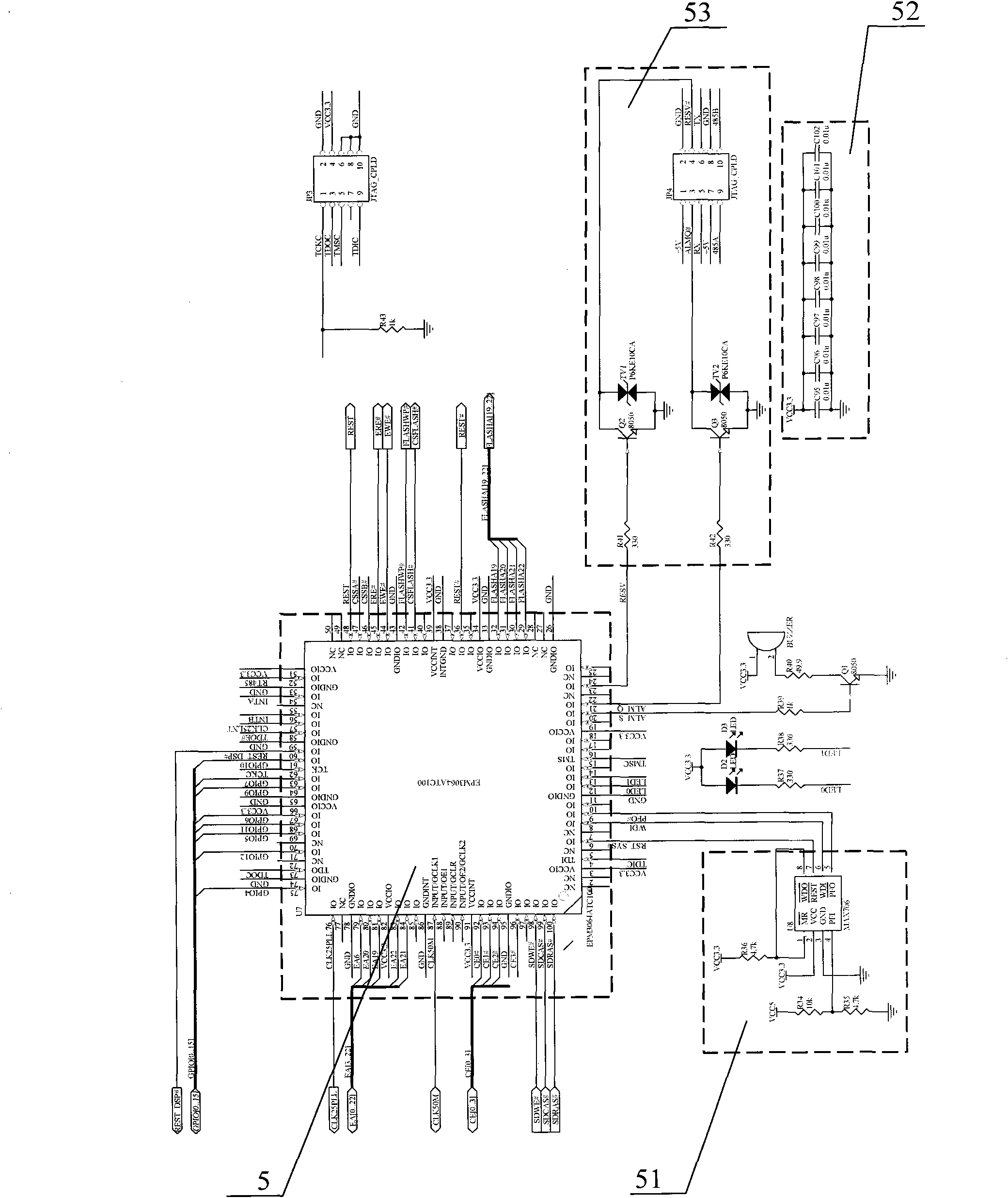
[0033] by attached figure 1 , figure 2 , image 3 , Figure 4 , Figure 5 , Image 6 , Figure 7 , Figure 8 Shown, a kind of road surface deceleration belt vehicle-mounted early warning device, comprises installing CCD camera 1 to connect frequency decoding chip 3 at automobile front end, and frequency decoding chip 3 passes through 1 2 The C bus is connected to the DSP chip 4, and is connected to the SDRAM memory chip 2 and the CPLD chip 5 through wires; the SDRAM memory chip 2 is connected to the DSP chip 4 and the FLASH chip 10 respectively, and is connected to the CPLD chip 5 through several interfaces; the CPLD chip 5 is also connected to the FLASH Chip 10 is connected to DSP chip 4 through several interfaces; DSP chip 4 is also connected to FLASH chip 10 and central controller 6, and central controller 6 is connected to voice chip 8 and LCD display screen 7, and voice chip 8 is connected to speaker 9; Install the CCD camera 1 to shoot the image signal of the spe...


PUM


Abstract

The invention discloses a road surface deceleration strip vehicle-mounted early warning device. The front end of an automobile is provided with a CCD camera to shoot a road surface deceleration strip image signal; the data is stored into a SDRAM memory chip by a video decoding chip; the confirmed image signal is transmitted into the front end of the CPLD chip control data for collection by the video decoding chip; a video output bus of the video decoding chip is connected with the data bus of a DSP chip; the collected data is processed by the DSP chip; whether the collected image is the deceleration strip is judged through identification and the result is sent to a central controller which controls a sound chip and an LCD display screen; the sound chip is connected with a speaker to send out the sound of deceleration strip in front and deceleration being needed; the deceleration strip image scheme is displayed on the LCD display screen, thus overcoming the defects that bump and vibration of the automobile body because drivers don not see clearly the deceleration strip in front to cause the automobile body to pass through the deceleration strip at a higher speed; and the early warning device is suitable for installation and use of various vehicles.

Description

technical field [0001] The invention relates to a vehicle-mounted early warning device for a road deceleration belt. Background technique [0002] Regarding the research on speed bumps, the speed reduction facilities have been developed to divide into speed reduction humps or mound belts, speed reduction platforms, speed reduction pads, speed reduction rumble belts, etc. according to their appearance and shape. The earliest deceleration device was used in Chatham City in the United States in 1906, and the maximum speed was limited to 30km / h. By 1990, speed bumps with a design speed limit of 30km / h were widely used in Britain, Sweden, Canada, Japan and other economically developed countries. In 1991, the International Society of Traffic Engineers gave guidelines for the design and use of road deceleration facilities. In view of foreign experience, my country's highway management departments and maintenance units have also begun to use a large number of speed bumps to enforc...

Claims


Application Information

Patent Timeline
Patent Type & Authority Applications(China)
IPC IPC(8): B60Q9/00B60R11/00H04N7/18
Inventor 杨书仪朱萍玉王乐何艳芳胡伟银
Owner HUNAN UNIV OF SCI & TECH
Why Eureka
Eureka Blog
Learn More