
Production method and device of copper tube used by conductive nozzle

A production method and the technology of the contact tip, which are applied in the direction of the mandrel, etc., can solve the problem that it is difficult to accurately control the deviation of the inner diameter and roundness of the copper tube for the contact tip, it is difficult to ensure the quality and yield of the copper tube for the contact tip, and the inner diameter of the tube. Hole size accuracy is difficult to control and other problems, to achieve the effect of automatic tracking and automatic reset, solve the problem of loading, high surface roughness

Inactive Publication Date: 2012-01-25
沈阳奥塔金属有限公司
View PDF0 Cites 0 Cited by
  • Summary
  • Abstract
  • Description
  • Claims
  • Application Information

AI Technical Summary

Problems solved by technology

There are two disadvantages in the production method of the copper tube for the contact tip. One is that the roughness of the inner surface of the tube deteriorates with the increase of the empty drawing passes of the tube blank; the other is that the dimensional accuracy of the inner hole of the tube is not easy to control.
With this production method, it is necessary to constantly face the interference of various unfavorable process factors in the production process, such as the dimensional deviation of the blank, the hardness of the blank, the uniformity of hardness, the mold parameters, lubrication, the amount of tensile deformation of the pass, the tensile Therefore, it is difficult to accurately control the inner diameter size deviation and roundness deviation of the copper tube for the contact tip with this method
For this reason, it is necessary to continuously adjust various process factors in the production process of the tube, but due to the complexity of the process factors, it is difficult to guarantee the quality and yield of the copper tube for the contact tip in the normal production process

Method used


Image

  • Production method and device of copper tube used by conductive nozzle
  • Production method and device of copper tube used by conductive nozzle
  • Production method and device of copper tube used by conductive nozzle

Examples


Embodiment Construction

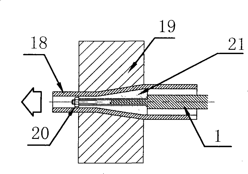
[0031] Such as figure 1 As shown, the fixed core head stretching method in the prior art is that the fixed core head 21 working in the drawing die 19 is connected with the fixed core rod 1 by the nut 20 . Since the size of the fixed mandrel 1 at the connection is always smaller than the outer diameter of the fixed mandrel 21, when the outer diameter of the fixed mandrel 21 is small to a certain size, the fixed mandrel 1 is caused by too small a cross-sectional dimension at the joint. The strength is not enough to realize the stretching of the copper tube for the contact tip.

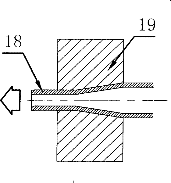
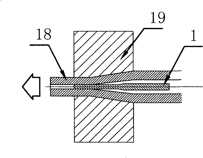
[0032] Such as figure 2 As shown, the copper tube billet is air-drawn on the existing linear tube and bar drawing machine, that is, the inner diameter of the copper tube is gradually obtained while reducing the outer diameter of the copper tube. There are two disadvantages in the production method of the copper tube for the contact tip. One is that the roughness of the inner surface of the tube deteri...


PUM


Abstract

The invention relates to a production method and a device of a copper tube used by a conductive nozzle. The invention is characterized in that the production method comprises the steps of installation, clamping and positioning of a core rod, material loading of the copper tube, stretching production and repeated stretching. A core head part of the core rod of the device and a pull rod part are in a whole body, a material loading sleeve pipe is sheathed on the core rod which is tightly clamped on a clamp head through the material loading sleeve pipe, a fixed support frame is arranged outside the material loading sleeve pipe and can do free movement relative to the support frame on a guide sleeve arranged on the fixed support frame, a trolly is arranged under the support frame, a front part movable spring mechanism and a back part fixed spring mechanism which are connected in series are arranged in the fixed support frame, the clamp head is connected with the front part movable spring mechanism, a universal shaft coupler is arranged behind the fixed support frame and is connected with a support seat through a screw rod, and the support seat is fixed on a base of a pull bed. The invention adopts a mode of directly forming the whole body of the core head and the pull rod in an inner hole of the copper tube, and the problem of direct forming of the inner diameter of the copper tube of the conductive nozzle with the inner diameter between phi 1 and phi 3 mm is solved.

Description

technical field [0001] The present invention relates to a production method and device for copper tubes, in particular to a production method and device for producing copper tubes for conductive tips on a linear stretching machine, belonging to the technical field of copper tube processing and production, and the present invention can also be applied In the production of other small-hole thick-walled copper pipes. Background technique [0002] The important use of the copper tube for the contact tip is to produce the contact tip for carbon dioxide gas shielded welding (hereinafter referred to as the contact tip). The contact tip is an important welding consumable part on the carbon dioxide gas shielded welding machine, and its material is red copper, phosphorus deoxidized copper, chrome bronze, zirconium bronze, silver copper and chromium zirconium bronze, etc. Copper pipes used for the production of contact tips usually have an outer diameter of Ф6-Ф12 mm and an inner diam...

Claims


Application Information

Patent Timeline
Patent Type & Authority Patents(China)
IPC IPC(8): B21C1/24B21C1/32B21C1/34B21C3/16
Inventor 周晓辉
Owner 沈阳奥塔金属有限公司
Learn More