Electrical connector

A technology for electrical connectors and docking connectors, which is applied in the directions of connections, circuits, and components of connecting devices, can solve the problems of high cost of the connector interface, complex chip design, and large size of the connector, and achieves a simple structural design. , The effect of easy design and strong anti-interference ability

Inactive Publication Date: 2012-07-04
FOXCONN (KUNSHAN) COMPUTER CONNECTOR CO LTD +1
View PDF5 Cites 0 Cited by
  • Summary
  • Abstract
  • Description
  • Claims
  • Application Information

AI Technical Summary

Problems solved by technology

[0004] From the above analysis, it can be seen that the functions corresponding to the conductive terminals of the existing C-type HDMI connector are complex and diverse, and the corresponding chip design is also very complicated, which leads to the high interface cost of using this type of connector and the relatively large size of the connector. Big
In addition, there is only one ground terminal (G) between two adjacent pairs of differential signal terminals (D+, D-), and relatively large crosstalk (Cross-talk) is likely to occur between the two pairs of differential signal terminals (D+, D-). )

Method used


Image

  • Electrical connector
  • Electrical connector
  • Electrical connector

Examples


Embodiment Construction

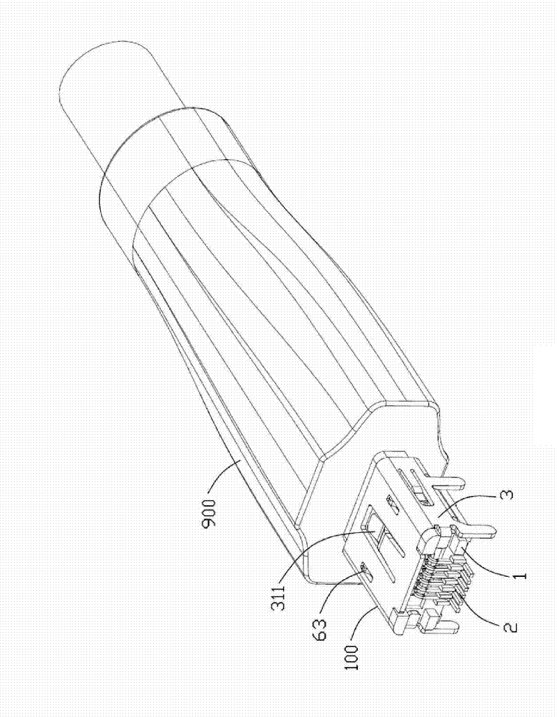
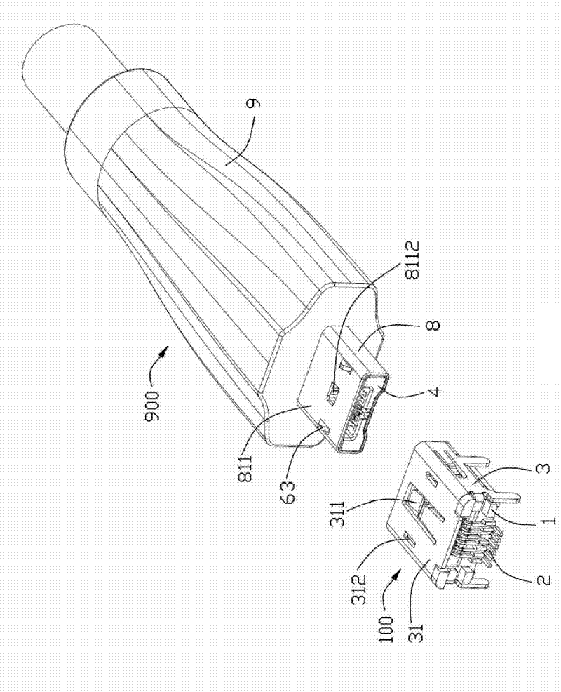
[0019] see figure 1 and figure 2 As shown, the electrical connector of the present invention includes a plug connector 900 (hereinafter referred to as the plug 900) and a socket connector 100 (hereinafter referred to as the socket 100), and the plug 900 and the socket 100 form a mutually insertable butt joint connection. device.

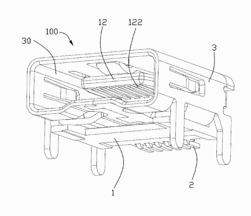
[0020] see Figure 3 to Figure 6 As shown, the socket 100 includes a first body 1, a plurality of first conductive terminals 2 held on the first body 1, and a first shielding shell 3 covering the first body 1. The first shielding shell 3 A first receiving space 30 for receiving the mating plug 900 is provided.

[0021] The first body 1 includes a first base 11 and a first tongue 12 protruding forward from the first base 11 . The first tongue 12 extends along the horizontal direction, and includes an upper surface 121 and a lower surface 122 opposite to the upper surface 121 . A protruding portion 1211 protruding upward is formed on the rear end...


PUM


Abstract

The invention relates to an electrical connector which comprises a body, a plurality of conductive terminals fixed on the body and a metal shielding casing body for shielding the body. The shielding casing body is provided with an accommodation space for accommodating docking connectors, the body is provided with a base part and a tongue plate extending to the accommodation space from the base part, the conductive terminals comprise contact parts extending to the tongue plate, the contact parts are arranged at the same side of the tongue plate in a row, and the conductive terminals only comprise two pairs of differential signal terminals and a pair of grounding terminals positioned between the two pairs of the differential signal terminals. The electrical connector has simple structure, strong anti-jamming capability and lower cost.

Description

【Technical field】 [0001] The invention relates to an electrical connector, in particular to an electrical connector capable of transmitting high-frequency signals. 【Background technique】 [0002] For the prior art related to the present invention, please refer to Japanese Artisan Patent Registration No. D1290558 issued on January 9, 2007, which discloses a C-type HDMI connector, which includes: an insulating body, which is held on the insulating body The 19 conductive terminals and the shielding shell covering the periphery of the insulating body. Wherein, the insulating body is provided with a horizontally extending tongue plate, and the lower surface of the tongue plate is provided with a plurality of terminal receiving grooves arranged at intervals. The conductive terminal is provided with a holding portion fixed to the insulating body, a welding portion extending out of the insulating body, and a contact portion accommodated in the terminal receiving groove. Looking in...

Claims


Application Information

Patent Timeline
Patent Type & Authority Patents(China)
IPC IPC(8): H01R13/02H01R13/646H01R13/648
Inventor 王陈喜韩洪强朱自强
Owner FOXCONN (KUNSHAN) COMPUTER CONNECTOR CO LTD
Why Eureka
Try Eureka