
Method for diagnosing deformation of transformer winding based on frequency response characteristics

A transformer winding and diagnostic method technology, applied in the direction of instruments, measuring electrical variables, measuring devices, etc., can solve problems such as difficult specifications, difficult maintenance decisions, and differences, and achieve the effect of easy implementation and unique diagnostic results

Active Publication Date: 2010-09-15
CHINA ELECTRIC POWER RES INST +1
View PDF3 Cites 25 Cited by
  • Summary
  • Abstract
  • Description
  • Claims
  • Application Information

AI Technical Summary

Problems solved by technology

For experienced professionals, this method can achieve high judgment accuracy, but this pure experience method has obvious shortcomings: on the one hand, it requires a high level of experience for analysts, and it is difficult to be competent without experience or insufficient experience; On the one hand, due to the dispersion and uncertainty of experience, this method is difficult to standardize, and different analysts may draw different analysis conclusions, which brings certain difficulties to maintenance decision-making

Method used


Image

  • Method for diagnosing deformation of transformer winding based on frequency response characteristics
  • Method for diagnosing deformation of transformer winding based on frequency response characteristics
  • Method for diagnosing deformation of transformer winding based on frequency response characteristics

Examples


Embodiment Construction

[0017] The present invention will be described in detail below in conjunction with the accompanying drawings and embodiments.

[0018] The frequency response fingerprint is to apply a sine wave voltage U with a variable frequency at one end of the transformer winding 1 , the other end of the transformer winding is connected to a resistor in series and grounded, and the voltage U will be generated on the resistor under the excitation of the voltage source 2 , put H(f)=201n(U 2 / U 1 ) with the change curve of 1kHz ~ 1MHz frequency is called the frequency response fingerprint, referred to as the frequency response fingerprint.

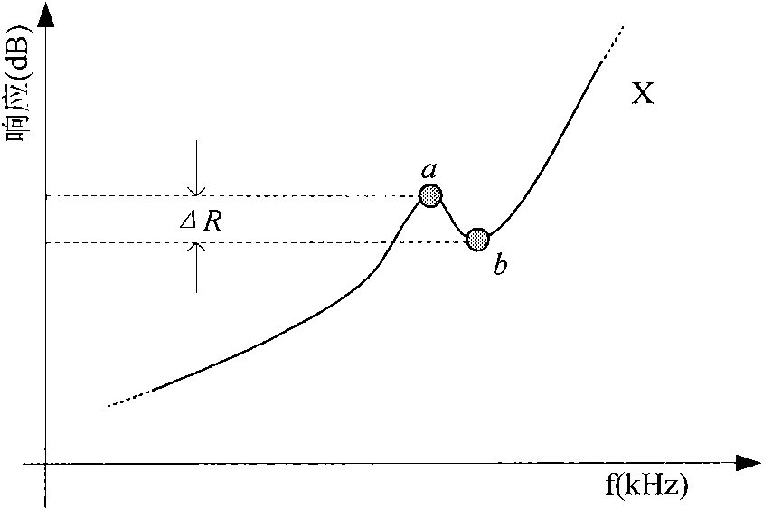
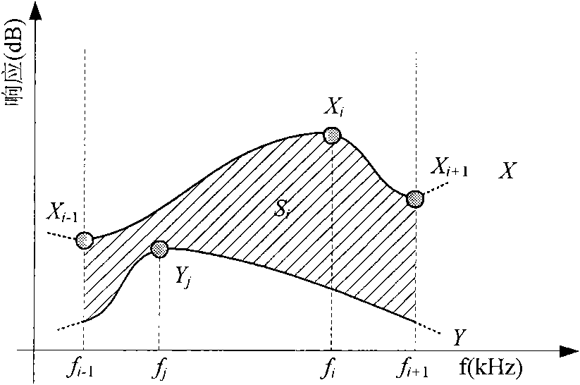
[0019] Such as figure 1 As shown, the present invention is based on a large number of extreme points related to the transformer winding structure contained in the frequency response fingerprint of the transformer winding. These extreme points are the basic characteristics of the frequency response fingerprint. When the transformer winding is deformed, ...


PUM


Abstract

The invention relates to a method for diagnosing deformation of a transformer winding based on frequency response characteristics. The method comprises the following steps of: (1) respectively acquiring a frequency response fingerprint of a winding to be diagnosed of a three-phase winding at the same voltage side of a transformer and an original frequency response fingerprint thereof; (2) judging characteristic points of the frequency response fingerprint of the winding to be diagnosed and the original frequency response fingerprint; (3) calculating amplitude difference factors of all characteristics on the original frequency response fingerprint; (4) calculating frequency difference factors of all characteristics points on the original frequency response fingerprint; (5) obtaining characteristic difference factors of the original frequency response fingerprint and the frequency response fingerprint of the winding to be diagnosed according to the amplitude difference factors and the frequency difference factors; and (6) judging whether the transformer winding generates deformation or not according to a characteristic difference factor judgment criterion. In the invention, whether the transformer winding generates the deformation or not is judged according to the characteristic points of the frequency response fingerprint of the transformer winding, therefore, whether the transformer winding generates the deformations or not can be accurately judged independent of experiences of professional staff. The invention can be not only applied to the analysis of frequency response fingerprint data, but also applied in the analysis of other similar data.

Description

technical field [0001] The invention relates to a transformer winding deformation diagnosis method, in particular to a transformer winding deformation diagnosis method based on frequency response characteristics. Background technique [0002] The axial or radial dimensional changes of power transformer windings under the action of mechanical force or electrodynamic force usually manifest as local twisting, bulging or displacement of windings. When the transformer is subjected to short-circuit current impact or impact during transportation, winding deformation may occur, which will directly affect the safe operation of the transformer. With the in-depth development of condition-based maintenance of power transmission and transformation equipment, the test results of transformer winding deformation have gradually become one of the important indicators for judging the operating conditions of transformers. [0003] Frequency response analysis is an important method for diagnosi...

Claims


Application Information

Patent Timeline
IPC IPC(8): G01R31/06
Inventor 许渊刘有为高克利毕建刚邓彦国
Owner CHINA ELECTRIC POWER RES INST
Learn More